
| Workshop | Empennage | Wings | Fuselage | Contact |
| <-- November 2010 | January 2011 --> |
Chronological Updates, December, 2010
4 Dec 2010
Over the last few days I've managed to finish up the stiffeners on the right aileron, bringing it up to the same point I had the left aileron up to last week.
This brings both ailerons up to the priming bottleneck (along with the main wing spars), so it's time to get another section going. Coming up next, the outboard leading edges.
12 Dec 2010
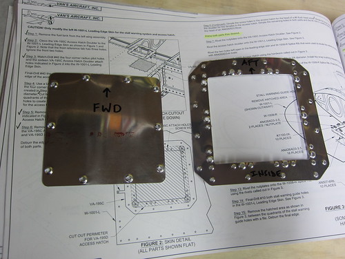
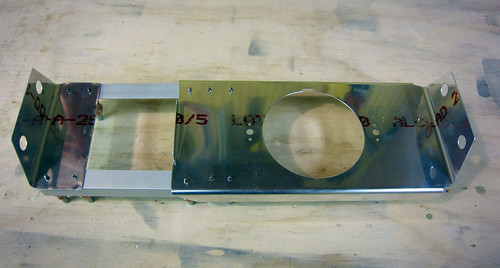
I've been doing a bit of work getting started on the leading edges. Most of it is not terribly photogenic. But just so I'll have something, here's a shot of the two plates that make up the stall warning mechanism bracket:
I had done most of the fab work on these two pieces awhile back, but the smaller holes call for a #31 drill, which I didn't have and wasn't available at the local hardware or home stores. So I finally, this weekend, went down to Harbor Freight and picked up an indexed drill set with #1-#60, A-Z, and all the fractionals up to 1/2" for $14. Nice. Now when these weird-sized holes that only exist once in the whole plane show up, I'll have a (low-quality) drill bit ready.
Anyway, now these two pieces are ready for priming. When the time comes, I'll be able to complete the leading-edge portions of Chapter 19 of the plans (stall warning) while the internal space where they go is still easy to access, rather than having to reach through the access hole on the bottom of the wing to adjust this mechanism.
In addition to these two tiny parts, I did manage to get all of the leading edge ribs fluted and the J-stiffeners cut to length. The four ribs that get their aft flanges modified have also been snipped. No pics of this.
The next step was to build the cradle, and I was procrastinating on this for a few reasons. For starters, I didn't have a jigsaw with which to cut out the templates on the lid of the shipping crate. This problem has been rectified. Next, when I opened the shipping crate, the lid cracked about 6" in one spot that just happened to pass right through the thinnest part of one of the leading edge cradle templates. Great. Tonight, I cut out the templates and predictably the one with the crack snapped in two almost immediately.
Luckily, the way it cracked left a large surface area onto which I applied wood glue and clamped the two halves back together. If this doesn't prove strong enough (I think it will), I'll just screw a backing board onto the bottom edge of this one.
18 Dec 2010
Yesterday it snowed so much that work called a snow day, and today the clouds were still low so my planned flying excursion was cancelled. Instead, I got a bunch of work done on the leading edges. First, I found a couple of old 2x4's in the garage and used them to build the side rails for the leading edge cradle. Then I took a die grinder to the fuel tank skins to separate the skin splice strip. Next, I put a small Scotchbrite wheel on the die grinder and dressed all of the edges on all parts (except the right-side leading edge skin, which hasn't been taken out of the garage yet).
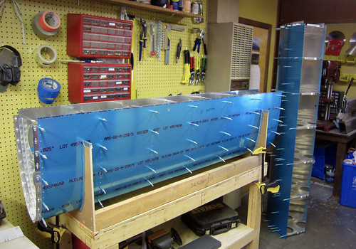
With all of that preparatory work out of the way, it was finally time to do the initial assembly on the left-side leading edge.
The only issue with the new cradle was that the two old 2x4s were really warped, so to get it to lay flat I had to clamp it to the table. Getting the holes to line up between the skin and the ribs was a challenge. And even with all of the holes cleco'd, I couldn't get the forward most holes to line up on any of the ribs. Not sure what to do about that yet.
I proceeded with the J-stiffener, which was exactly the right length. The centerline I had previously drawn on it stayed perfectly aligned in the skin holes without any work from me, so this should be considerably easy to work with than the tail cone J-stiffeners (which I had to manhandle to get to line up right). My dad, who is visiting for the week, helped me dril out the holes between stiffener and skin.
The last piece to go on was the skin splice strip, and this was the most difficult piece of the whole assembly. It is wedged between the inboard rib and the skin, which means that the holes in three pieces have to line up before the cleco has any chance of going through. Again, there were a few holes at the forward end that I couldn't get to line up at all. They're close enough that I think I can just match drill them and they'll be essentially round.
This is all ten parts that make up the leading edge assembly per the plans; the next step is to match drill all of the skin holes. I'm awaiting delivery of the landing light kits from Duckworks so that they can be installed before finalizing the leading edge assembly. I'll also be doing some of the stall warning modifications prior to priming these parts. And, of course, there's always the right-side leading edge to contend with as well.
25 Dec 2010
I spent some time over the last couple days doing little bits and pieces for the leading edges. On the left side, I got the stall warning access hatch doubler match drilled.
With that done, I remved it and cut off the two alignment tabs. Then I drilled the four corner holes for the hatch cutout in the skin.
I don't have a fine-tooth blade for my jigsaw meant for cutting thin metal like this, so I'll have to wait on finishing the hatch hole. Instead, I finished off the hatch cover itself and the doubler by deburring all holes and dimpling.
These two parts are now ready for alodining and priming. The next small task I took care of was the stall warning vane slot. This starts as just two small 3/32 holes in the skin which I enlared to #10, then filed out the material between the holes.
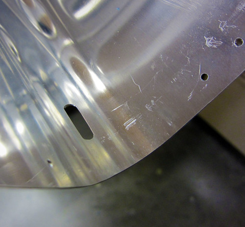
I'm really happy with how clean this hole came out, especially for being hand-carved with a small jeweler's file.
I set aside the left leading edge and put the right side leading edge together remarkably quick. Both assemblies are now complete per the plans up through the step where they are to be fully disassembled so that the deburring and dimpling phase can begin.
However, there are a couple of customizations I want to build in before I disassemble anything. The first is a CPC connector in the inboard bay on the left side. This will service the stall warning switch as well as any accessory I might eventually wire into this bay. The most likely candidate here would be a down-firing camera attached to the access hatch cover. I'm not planning on building that in initially, but I like to keep my options open. Running a few extra wires and adding a CPC will make adding such a thing really easy in the future.
The other customization for the leading edges is the inclusion of Duckworks Aviation leading edge PAR-36 landing light mounts. I haven't decided if I'm going to go with HID lamps or shell out for the (very expensive) LED lamps, so for now I'm just going to install the mount brackets. I've already ordered them but they are taking their time getting to me. I want to install those while everything is still fully assembled, so I'm putting the leading edges on hold until the Duckworks parts arrive.
One last get-ahead task I did before moving the leading edges to the garage was to take out the splice strips and do the dimpling and countersinking for the nutplates. Reinstalled the splice strips for storage. The results can be seen in the image above if you zoom in.
28 Dec 2010
The Duckworks Aviation leading edge landing light kits showed up last night, so this morning I started a bit of work on them.
The first step was to make the template for the rib holes. This was a simple matter of glueing the included piece of paper onto some cardboard, cutting out along the line, poking the two holes through the cardboard, then marking the ribs through the holes.
Once the center holes are marked, they are drilled out to accept #10 bolts and then the nutplate attachment holes are added using a nutplate as a template.
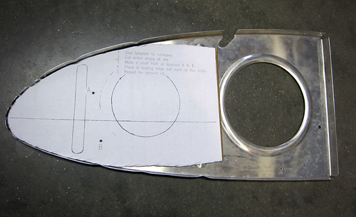
I got both of the ribs for the right wing modified in this way, then re-assembled them into the leading edge for the next step. This was to cut out the lens hole template and tape it onto the skin.
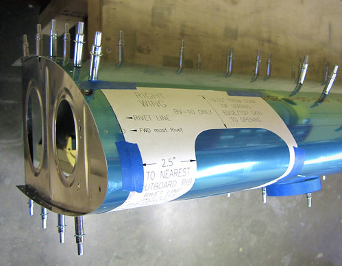
Again, the kit makes it very easy; no special measurements were required and it took very little time to get everything aligned properly. With the template in place, I just traced around the open hole with a thin sharpee and then removed the template. The next step is to cut out the traced line, either with a jigsaw or snips. I decided that snips end up bending the metal too much so I'm going to try a jigsaw, but for that I need a finer blade than I have so this step will have to wait. I did, however, drill a big 3/4" pilot hole in the center using a unibit.
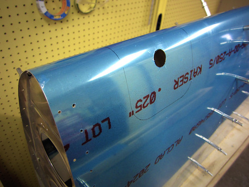
It was a bit nerve racking putting a big hole in the skin of the airplane that isn't in the plans, but this isn't the first time I've done this sort of thing and this product has a strong pedigree in the RV-10 community so I'm not too worried about it.
Now I'm off to Harbor Freight to find a good thin metal jigsaw blade.
29 Dec 2010
Got a bunch of work done on the right-side landing light assembly today. Started the day down in Albuqureque, so after dropping Nina off at the airport, I swung by Harbor Freight and picked up a pneumatic body saw and some fine 32tpi metal cutting blades. This was the tool I was missing to be able to make the landing light lens cutouts in the leading edges.
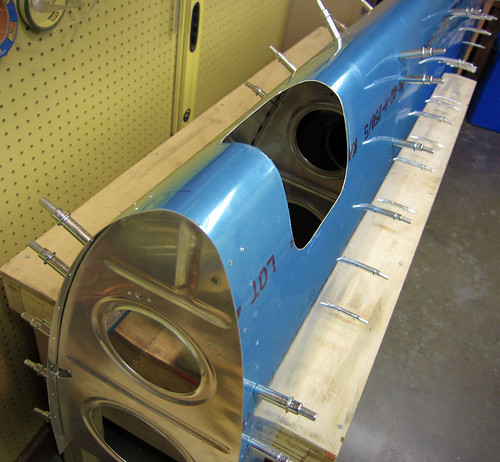
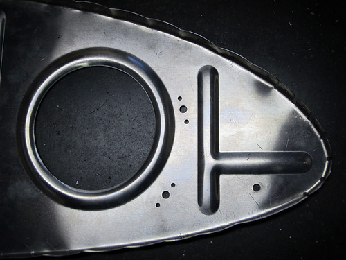
It took awhile to get it cut and dressed nicely, but in the end it looks really good. With the hole made, I started in on the light bracket itself. This involves separating the two sides of the bracket from each other, then fabricating a couple of angle bars to connect them. Here's a shot of the four pieces cleco'd together:
...and here's a shot of it test-fitted into the leading edge (as seen from aft):
Everything looked good in the test fit, so I deburred all the holes and got the nutplate attachment holes dimpled. Now all parts of that bracket are ready for surface treatment and priming.
Moving on to the lens retaining brackets. I got the top side pieces ready for priming without much difficulty. The countersinking of the really thin piece was a bit ugly, and to be honest I'm not sure why they don't just use a AD470 rivet there instead of the flush one, since the machine head of the rivet sticks out into free space inside the leading edge anyway... Regardless, those two pieces are also on the ready-for-priming pile. Here's a shot of the thin piece just after I finished match-drilling it to the skin:
I started to do the bottom retainer, but the instructions had some serious problems here and I couldn't continue without clarification. For starters, they state that the corner holes and rivets aren't used, so don't put the rivets in. The pictures all show the rivets; the piece they sent me doesn't even have the holes. I'm going to assume the verbage is correct on this one and that the photos are out of date (as it states). However, then it says to line the bottom strip up with the bottom edge of the hole, unlike in the picture (ok, fine). And it follows that up with a statement to do it just like it was done for the top retainer (which is what the picture shows). So it is internally inconsistent. I think what they want is for the strip and hole edge to line up, like this:
But I want to make sure before I drill any more holes in the skin. So this bit is on hold until I hear back from Duckworks. It's not much of a hold-up, since all that is left is this piece and the other strip for the bottom retaininer, then everything for the landing light is ready for priming. And the lens fitting won't get done until the entire leading edge is assembled, anyway.
Over the last few days I've managed to finish up the stiffeners on the right aileron, bringing it up to the same point I had the left aileron up to last week.
This brings both ailerons up to the priming bottleneck (along with the main wing spars), so it's time to get another section going. Coming up next, the outboard leading edges.
12 Dec 2010
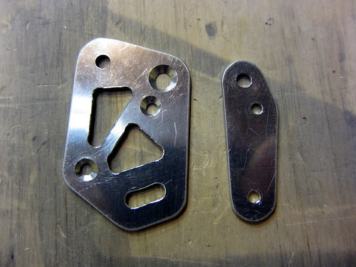
I've been doing a bit of work getting started on the leading edges. Most of it is not terribly photogenic. But just so I'll have something, here's a shot of the two plates that make up the stall warning mechanism bracket:
I had done most of the fab work on these two pieces awhile back, but the smaller holes call for a #31 drill, which I didn't have and wasn't available at the local hardware or home stores. So I finally, this weekend, went down to Harbor Freight and picked up an indexed drill set with #1-#60, A-Z, and all the fractionals up to 1/2" for $14. Nice. Now when these weird-sized holes that only exist once in the whole plane show up, I'll have a (low-quality) drill bit ready.
Anyway, now these two pieces are ready for priming. When the time comes, I'll be able to complete the leading-edge portions of Chapter 19 of the plans (stall warning) while the internal space where they go is still easy to access, rather than having to reach through the access hole on the bottom of the wing to adjust this mechanism.
In addition to these two tiny parts, I did manage to get all of the leading edge ribs fluted and the J-stiffeners cut to length. The four ribs that get their aft flanges modified have also been snipped. No pics of this.
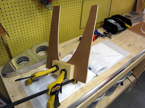
The next step was to build the cradle, and I was procrastinating on this for a few reasons. For starters, I didn't have a jigsaw with which to cut out the templates on the lid of the shipping crate. This problem has been rectified. Next, when I opened the shipping crate, the lid cracked about 6" in one spot that just happened to pass right through the thinnest part of one of the leading edge cradle templates. Great. Tonight, I cut out the templates and predictably the one with the crack snapped in two almost immediately.
Luckily, the way it cracked left a large surface area onto which I applied wood glue and clamped the two halves back together. If this doesn't prove strong enough (I think it will), I'll just screw a backing board onto the bottom edge of this one.
18 Dec 2010
Yesterday it snowed so much that work called a snow day, and today the clouds were still low so my planned flying excursion was cancelled. Instead, I got a bunch of work done on the leading edges. First, I found a couple of old 2x4's in the garage and used them to build the side rails for the leading edge cradle. Then I took a die grinder to the fuel tank skins to separate the skin splice strip. Next, I put a small Scotchbrite wheel on the die grinder and dressed all of the edges on all parts (except the right-side leading edge skin, which hasn't been taken out of the garage yet).
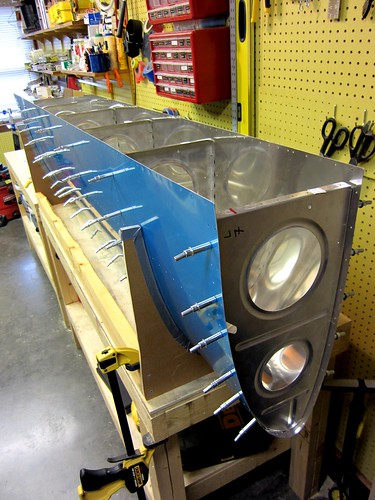
With all of that preparatory work out of the way, it was finally time to do the initial assembly on the left-side leading edge.
The only issue with the new cradle was that the two old 2x4s were really warped, so to get it to lay flat I had to clamp it to the table. Getting the holes to line up between the skin and the ribs was a challenge. And even with all of the holes cleco'd, I couldn't get the forward most holes to line up on any of the ribs. Not sure what to do about that yet.
I proceeded with the J-stiffener, which was exactly the right length. The centerline I had previously drawn on it stayed perfectly aligned in the skin holes without any work from me, so this should be considerably easy to work with than the tail cone J-stiffeners (which I had to manhandle to get to line up right). My dad, who is visiting for the week, helped me dril out the holes between stiffener and skin.
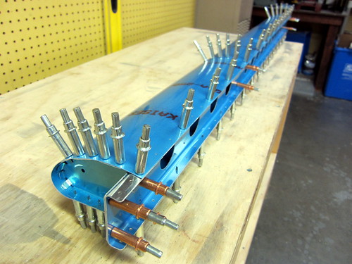
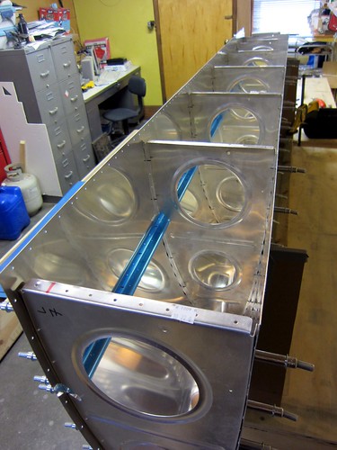
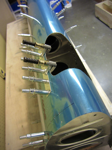
The last piece to go on was the skin splice strip, and this was the most difficult piece of the whole assembly. It is wedged between the inboard rib and the skin, which means that the holes in three pieces have to line up before the cleco has any chance of going through. Again, there were a few holes at the forward end that I couldn't get to line up at all. They're close enough that I think I can just match drill them and they'll be essentially round.
This is all ten parts that make up the leading edge assembly per the plans; the next step is to match drill all of the skin holes. I'm awaiting delivery of the landing light kits from Duckworks so that they can be installed before finalizing the leading edge assembly. I'll also be doing some of the stall warning modifications prior to priming these parts. And, of course, there's always the right-side leading edge to contend with as well.
25 Dec 2010
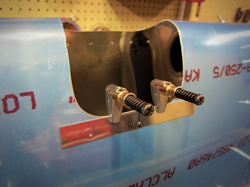
I spent some time over the last couple days doing little bits and pieces for the leading edges. On the left side, I got the stall warning access hatch doubler match drilled.
With that done, I remved it and cut off the two alignment tabs. Then I drilled the four corner holes for the hatch cutout in the skin.
I don't have a fine-tooth blade for my jigsaw meant for cutting thin metal like this, so I'll have to wait on finishing the hatch hole. Instead, I finished off the hatch cover itself and the doubler by deburring all holes and dimpling.
These two parts are now ready for alodining and priming. The next small task I took care of was the stall warning vane slot. This starts as just two small 3/32 holes in the skin which I enlared to #10, then filed out the material between the holes.
I'm really happy with how clean this hole came out, especially for being hand-carved with a small jeweler's file.
I set aside the left leading edge and put the right side leading edge together remarkably quick. Both assemblies are now complete per the plans up through the step where they are to be fully disassembled so that the deburring and dimpling phase can begin.
However, there are a couple of customizations I want to build in before I disassemble anything. The first is a CPC connector in the inboard bay on the left side. This will service the stall warning switch as well as any accessory I might eventually wire into this bay. The most likely candidate here would be a down-firing camera attached to the access hatch cover. I'm not planning on building that in initially, but I like to keep my options open. Running a few extra wires and adding a CPC will make adding such a thing really easy in the future.
The other customization for the leading edges is the inclusion of Duckworks Aviation leading edge PAR-36 landing light mounts. I haven't decided if I'm going to go with HID lamps or shell out for the (very expensive) LED lamps, so for now I'm just going to install the mount brackets. I've already ordered them but they are taking their time getting to me. I want to install those while everything is still fully assembled, so I'm putting the leading edges on hold until the Duckworks parts arrive.
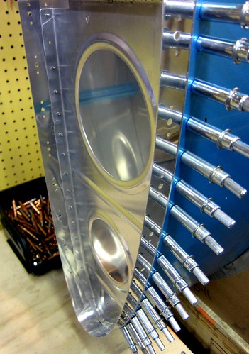
One last get-ahead task I did before moving the leading edges to the garage was to take out the splice strips and do the dimpling and countersinking for the nutplates. Reinstalled the splice strips for storage. The results can be seen in the image above if you zoom in.
28 Dec 2010
The Duckworks Aviation leading edge landing light kits showed up last night, so this morning I started a bit of work on them.
The first step was to make the template for the rib holes. This was a simple matter of glueing the included piece of paper onto some cardboard, cutting out along the line, poking the two holes through the cardboard, then marking the ribs through the holes.
Once the center holes are marked, they are drilled out to accept #10 bolts and then the nutplate attachment holes are added using a nutplate as a template.
I got both of the ribs for the right wing modified in this way, then re-assembled them into the leading edge for the next step. This was to cut out the lens hole template and tape it onto the skin.
Again, the kit makes it very easy; no special measurements were required and it took very little time to get everything aligned properly. With the template in place, I just traced around the open hole with a thin sharpee and then removed the template. The next step is to cut out the traced line, either with a jigsaw or snips. I decided that snips end up bending the metal too much so I'm going to try a jigsaw, but for that I need a finer blade than I have so this step will have to wait. I did, however, drill a big 3/4" pilot hole in the center using a unibit.
It was a bit nerve racking putting a big hole in the skin of the airplane that isn't in the plans, but this isn't the first time I've done this sort of thing and this product has a strong pedigree in the RV-10 community so I'm not too worried about it.
Now I'm off to Harbor Freight to find a good thin metal jigsaw blade.
29 Dec 2010
Got a bunch of work done on the right-side landing light assembly today. Started the day down in Albuqureque, so after dropping Nina off at the airport, I swung by Harbor Freight and picked up a pneumatic body saw and some fine 32tpi metal cutting blades. This was the tool I was missing to be able to make the landing light lens cutouts in the leading edges.
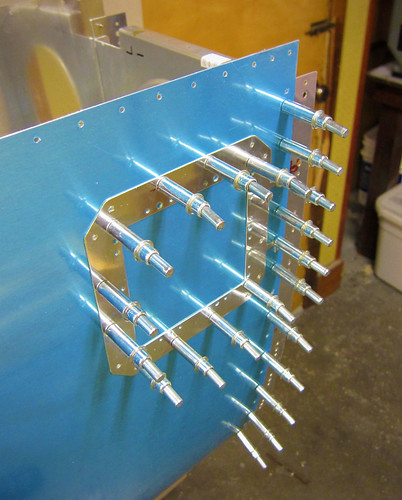
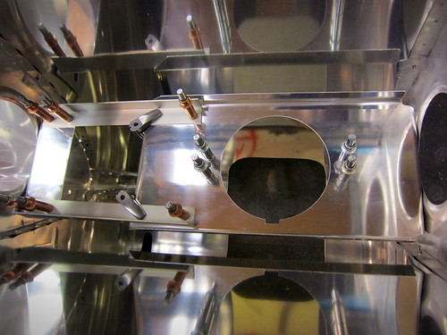
It took awhile to get it cut and dressed nicely, but in the end it looks really good. With the hole made, I started in on the light bracket itself. This involves separating the two sides of the bracket from each other, then fabricating a couple of angle bars to connect them. Here's a shot of the four pieces cleco'd together:
...and here's a shot of it test-fitted into the leading edge (as seen from aft):
Everything looked good in the test fit, so I deburred all the holes and got the nutplate attachment holes dimpled. Now all parts of that bracket are ready for surface treatment and priming.
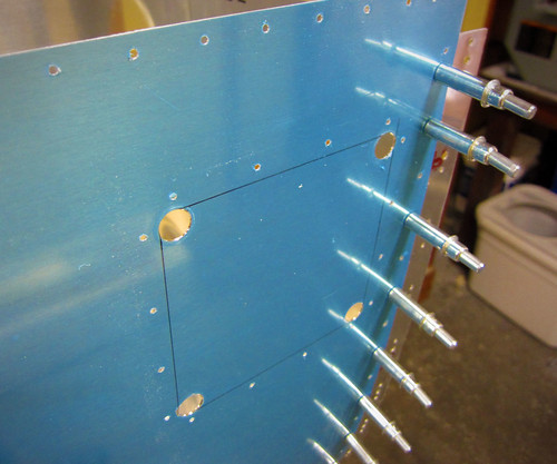
Moving on to the lens retaining brackets. I got the top side pieces ready for priming without much difficulty. The countersinking of the really thin piece was a bit ugly, and to be honest I'm not sure why they don't just use a AD470 rivet there instead of the flush one, since the machine head of the rivet sticks out into free space inside the leading edge anyway... Regardless, those two pieces are also on the ready-for-priming pile. Here's a shot of the thin piece just after I finished match-drilling it to the skin:
I started to do the bottom retainer, but the instructions had some serious problems here and I couldn't continue without clarification. For starters, they state that the corner holes and rivets aren't used, so don't put the rivets in. The pictures all show the rivets; the piece they sent me doesn't even have the holes. I'm going to assume the verbage is correct on this one and that the photos are out of date (as it states). However, then it says to line the bottom strip up with the bottom edge of the hole, unlike in the picture (ok, fine). And it follows that up with a statement to do it just like it was done for the top retainer (which is what the picture shows). So it is internally inconsistent. I think what they want is for the strip and hole edge to line up, like this:
But I want to make sure before I drill any more holes in the skin. So this bit is on hold until I hear back from Duckworks. It's not much of a hold-up, since all that is left is this piece and the other strip for the bottom retaininer, then everything for the landing light is ready for priming. And the lens fitting won't get done until the entire leading edge is assembled, anyway.
| <-- November 2010 | January 2011 --> |