
| Workshop | Empennage | Wings | Fuselage | Contact |
Static Wicks for the RV-10
If you decide, as I did, that P-static presents a risk to radio
reception and possibly to the integrity of the moving joints of the
aircraft's control surfaces, then you'll want to install static wicks
and bonding straps. This page covers the installation required for
static wicks on the rudder, elevators, ailerons, and wingtips of the RV-10.
The assembly sequence described here uses screws and anchor nuts to fasten the wicks to the aircraft rather than the conventional blint rivet solution. As a consequence, you are required to install some extra hardware before final riveting of the various sub-assemblies in the plane. The result is static wicks that are cleanly removable/replaceable as necessary.
Dayton-Granger recomments two wicks at the top of the rudder trailing edge, two at the outboard end of the trailing edge of each elevator, and three at the outboard end of the trailing edge of each wing—the recommended 12" spacing between wicks puts the inboard-most wing wick on the aileron.
The 16165 wicks aren't the cheapest; I was able to get them for $42 each at skygeek.com. The recommended loadout for the RV-10 is twelve wicks total, so you're looking at over $500 just for wick hardware. Half go on the empennage and half on the wings, so if you think of it as two $250 purchases separated by quite some time, it's a bit easier to swallow.
The 16165 wicks have two holes sized for #10 hardware with the forward hole being elongated to allow for a variety of screw separations. AN515-10 washer-head screws are a natural match. Specifically, the AN515-10R6 length is a good one to get. A good elastic-insert anchor nut for #10-32 hardware is the AN366F-1032A which I bought from Aircraft Spruce. In order to take advantage of the extremely low headroom environment inside the trailing edges of the RV-10, I bought some MS21080-3 one-lug elastic-insert anchor nuts as well for the aft-most screws.
The sections that follow will outline the installation procedure that I used for each of the relevant aircraft subassemblies.
In the RV-10, the rudder stiffeners are almost perfectly suited for the D-G recommendations. The top fairing contributes essentially zero height to the trailing edge, so the top rib's aft-most point is right at the top of the trailing edge. This rib makes a perfect location for the upper wick's attachment hardware.
The second stiffener down from the top is almost exactly 12" below the top rib, and thus it makes an excellent choice for a built-in structural reinforcement for the lower rudder wick.
Since both wicks locations have built-in doublers already, nothing more is required beyond the screws, anchor nuts, a few rivets, and the wick itself. Here is a picture of the anchor nuts sitting in place on the inside surface of the upper rib:
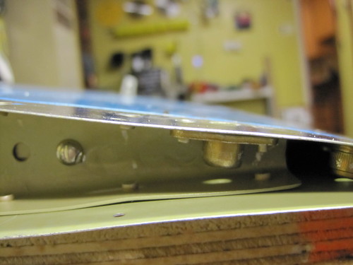
In this position, there is just enough headroom for the aft anchor nut, so the screw has to be sized just right so as not to protrude from the elastic side of the nut when tightened down. The AN515-10R6 is perhaps a bit too long for this. You may need to grind down a few milimeters off the aft screw to prevent putting a little dimple into the opposing skin (ask me how I know). Here is a side view showing how little clearance there is:
Note, however, that both of these pictures were taken with the hardware resting on the right-side skin. In practice, it makes a lot more sense to add the wicks to the left-side skin so that they add a bit to the generally-desireable right rudder effect. I used the right-side skins for testing the anchor nut head room because the stiffener was slightly taller on this side and was a better estimator of the total space available between the skins.
Once the locations for the rivet and screw holes are determined, I recommend making a hole template out of scrap sheet aluminum for the anchor nut hole pattern, then using that to drill the holes in the rudder skin and stiffeners. I didn't do this the first time through and the holes were a bit wonky as a result. Here are the holes for the lower of the two wicks:
And here is the same spot, from the other side, after the anchor nuts were installed:
Note that the rivets for the anchor nuts must be flush or the wick hardware can't sit flat against the skin. Also, the anchor nuts won't accept a dimpled hole. Thus, the skin/stiffener combo must be machine countersunk to accept the rivet. Because of the weird angle of the stiffener beneath the skin, I was not able to do this with my drill press and ended up doing it manually with my deburring tool and countersinking bit, one turn at a time and testing the fit of the rivet. In the end, I got great results. Once this is done for both locations, the wicks themselves can be screwed on for a test.
Once I had confirmed that I was happy with the installation, I removed the wicks and screws and set them aside for the duration of the RV-10 construction project. Won't need to install them again until the plane is ready to fly.
Unfortunately, there are no other internal structural members anywhere along the trailing edge (at least outboard of the trim tab). As a result, you'll need to fashion your own doubler for the inboard elevator static wicks as well as the aft anchor nut for the outboard wicks.
The aft anchor nut for the outboard wick is off the end of the flage for the tip piece, so it needs a doubler. For clearance reasons with the trailing edge extrusion, I used a one-lug anchor nut and mounted it perpendicular to the foreward anchor nut. I fabricated this small doubler out of a piece of scrap and used it as a template to drill the holes for the aft anchor nut:
The inboard wick has no underlying support rib to take advantage of, so I made a larger doubler that covered both anchor nuts as was able to include a couple of rivet holes just to add support for the doubler.
This doubler was used as a template for the inboard wick mounting holes, which are situated 12 inches inboard of the outboard holes, as per the Dayton Granger recommendations for the RV-10.
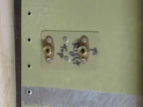
Once everything is primed, assembly is straightforward. Here is the installed inboard doubler and anchor nuts:
And here is the installed hardware for the aft outboard anchor nut:
Finally, there is the forward outboard anchor nut. The forward rivet is squeezable with a 4" narrow-head yoke, but the aft rivet has almost no clearance at all. I ended up using a thin chisel as a bucking bar and driving it with the rivet gun. It is almost certainly under-driven, but this is of little concern since this rivet is structurally redundant once the static wick is secured in place.
So here's the result for the outboard static wick holes:
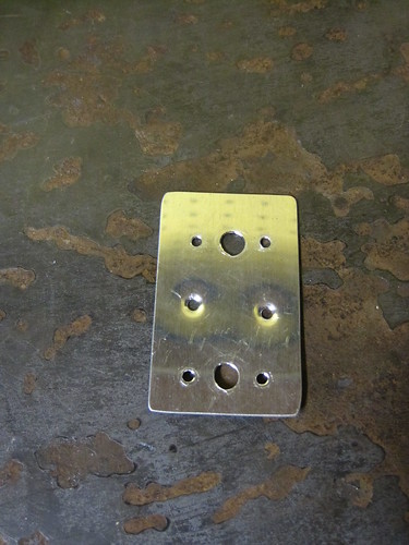
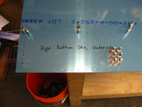
Because the wingtip is cramped inside, it will be somewhat difficult to mount anchor hardware inside very close to the trailing edge. Thus, the wicks on the wingtips will be a bit further forward than those on the elevators and rudder. For aesthetic reasons, the aileron wick needs to be correspondingly a bit more forward as well. This means that we can use standard anchor nuts for both holes. The modifications to the aileron stiffeners look like this:
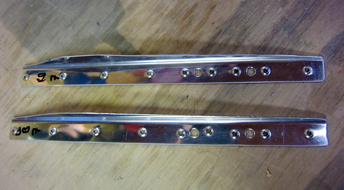
And the modified skin looks like this:
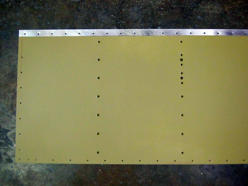
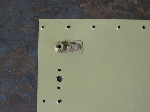
Finally, here's what the installed hardware looks like on the bottom aileron skin:
The assembly sequence described here uses screws and anchor nuts to fasten the wicks to the aircraft rather than the conventional blint rivet solution. As a consequence, you are required to install some extra hardware before final riveting of the various sub-assemblies in the plane. The result is static wicks that are cleanly removable/replaceable as necessary.
Parts Selection
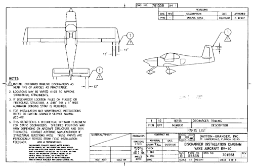
I selected the Dayton-Granger 16165 static wick part for a couple of reasons. First, they seem to be highly regarded by reviewers on the internet. Second, D-G has published a document showing exactly where and how many of the 16165 wicks are required for the RV-10: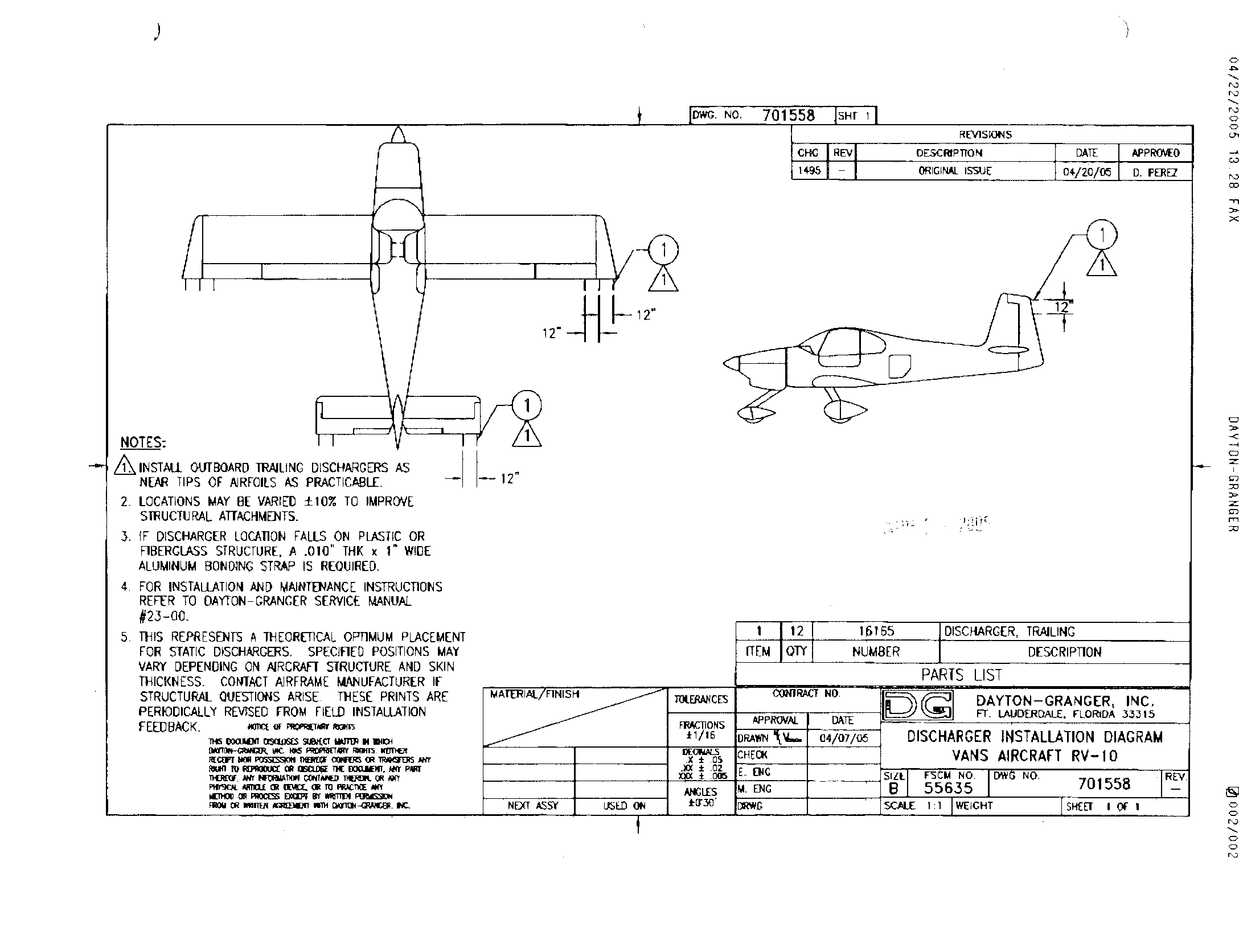
Dayton-Granger recomments two wicks at the top of the rudder trailing edge, two at the outboard end of the trailing edge of each elevator, and three at the outboard end of the trailing edge of each wing—the recommended 12" spacing between wicks puts the inboard-most wing wick on the aileron.
The 16165 wicks aren't the cheapest; I was able to get them for $42 each at skygeek.com. The recommended loadout for the RV-10 is twelve wicks total, so you're looking at over $500 just for wick hardware. Half go on the empennage and half on the wings, so if you think of it as two $250 purchases separated by quite some time, it's a bit easier to swallow.
The 16165 wicks have two holes sized for #10 hardware with the forward hole being elongated to allow for a variety of screw separations. AN515-10 washer-head screws are a natural match. Specifically, the AN515-10R6 length is a good one to get. A good elastic-insert anchor nut for #10-32 hardware is the AN366F-1032A which I bought from Aircraft Spruce. In order to take advantage of the extremely low headroom environment inside the trailing edges of the RV-10, I bought some MS21080-3 one-lug elastic-insert anchor nuts as well for the aft-most screws.
The sections that follow will outline the installation procedure that I used for each of the relevant aircraft subassemblies.
Rudder Static Wicks
The D-G installation diagram for the RV-10 indicates that the top rudder wick should be as close to the top of the trailing edge as possible, and that the lower one should be twelve inches away. It allows for a 10% change in these locations in order to take advantage of the availability of structural mounting positions.In the RV-10, the rudder stiffeners are almost perfectly suited for the D-G recommendations. The top fairing contributes essentially zero height to the trailing edge, so the top rib's aft-most point is right at the top of the trailing edge. This rib makes a perfect location for the upper wick's attachment hardware.
The second stiffener down from the top is almost exactly 12" below the top rib, and thus it makes an excellent choice for a built-in structural reinforcement for the lower rudder wick.
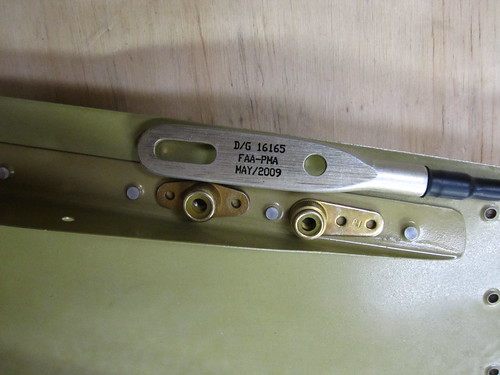
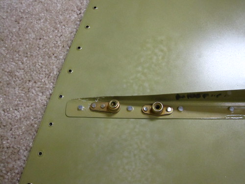
Since both wicks locations have built-in doublers already, nothing more is required beyond the screws, anchor nuts, a few rivets, and the wick itself. Here is a picture of the anchor nuts sitting in place on the inside surface of the upper rib:
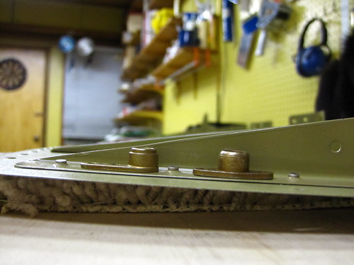
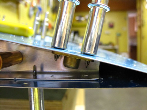
In this position, there is just enough headroom for the aft anchor nut, so the screw has to be sized just right so as not to protrude from the elastic side of the nut when tightened down. The AN515-10R6 is perhaps a bit too long for this. You may need to grind down a few milimeters off the aft screw to prevent putting a little dimple into the opposing skin (ask me how I know). Here is a side view showing how little clearance there is:
Note, however, that both of these pictures were taken with the hardware resting on the right-side skin. In practice, it makes a lot more sense to add the wicks to the left-side skin so that they add a bit to the generally-desireable right rudder effect. I used the right-side skins for testing the anchor nut head room because the stiffener was slightly taller on this side and was a better estimator of the total space available between the skins.
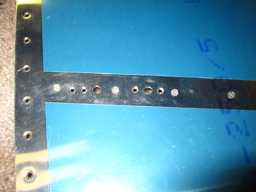
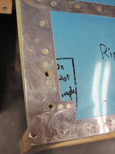
Once the locations for the rivet and screw holes are determined, I recommend making a hole template out of scrap sheet aluminum for the anchor nut hole pattern, then using that to drill the holes in the rudder skin and stiffeners. I didn't do this the first time through and the holes were a bit wonky as a result. Here are the holes for the lower of the two wicks:
And here is the same spot, from the other side, after the anchor nuts were installed:
Note that the rivets for the anchor nuts must be flush or the wick hardware can't sit flat against the skin. Also, the anchor nuts won't accept a dimpled hole. Thus, the skin/stiffener combo must be machine countersunk to accept the rivet. Because of the weird angle of the stiffener beneath the skin, I was not able to do this with my drill press and ended up doing it manually with my deburring tool and countersinking bit, one turn at a time and testing the fit of the rivet. In the end, I got great results. Once this is done for both locations, the wicks themselves can be screwed on for a test.
Once I had confirmed that I was happy with the installation, I removed the wicks and screws and set them aside for the duration of the RV-10 construction project. Won't need to install them again until the plane is ready to fly.
Elevator Static Wicks
The Dayton-Granger installation diagram calls for two static wicks at the outboard end of the trailing edges of each elevator asembly. As with the rudder, the wicks will attach via anchor nuts with elastic inserts. For the outboard wick, the tip rib makes a great intrinsic doubler. Here is where the forward anchor nut is attached:
Unfortunately, there are no other internal structural members anywhere along the trailing edge (at least outboard of the trim tab). As a result, you'll need to fashion your own doubler for the inboard elevator static wicks as well as the aft anchor nut for the outboard wicks.
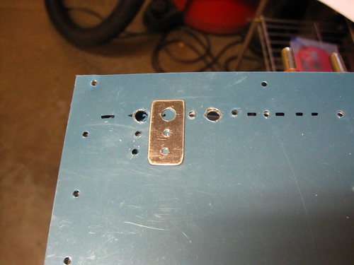
The aft anchor nut for the outboard wick is off the end of the flage for the tip piece, so it needs a doubler. For clearance reasons with the trailing edge extrusion, I used a one-lug anchor nut and mounted it perpendicular to the foreward anchor nut. I fabricated this small doubler out of a piece of scrap and used it as a template to drill the holes for the aft anchor nut:
The inboard wick has no underlying support rib to take advantage of, so I made a larger doubler that covered both anchor nuts as was able to include a couple of rivet holes just to add support for the doubler.
This doubler was used as a template for the inboard wick mounting holes, which are situated 12 inches inboard of the outboard holes, as per the Dayton Granger recommendations for the RV-10.
Once everything is primed, assembly is straightforward. Here is the installed inboard doubler and anchor nuts:
And here is the installed hardware for the aft outboard anchor nut:
Finally, there is the forward outboard anchor nut. The forward rivet is squeezable with a 4" narrow-head yoke, but the aft rivet has almost no clearance at all. I ended up using a thin chisel as a bucking bar and driving it with the rivet gun. It is almost certainly under-driven, but this is of little concern since this rivet is structurally redundant once the static wick is secured in place.
So here's the result for the outboard static wick holes:
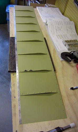
Aileron Static Wicks
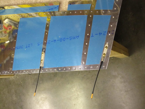
The Dayton-Granger layout advises that there be three static wicks in each wing, with 12" between each, starting as close to the outboard end of the trailing edge as possible. In the RV-10, this puts two of the wicks in the wingtip and one on the aileron. For simplicity's sake, I recommend putting the middle wick directly below the wingtip rib so that it has an intrinsic doubler (and something metal to attach to). The inboard wick is thus approximately 12" inboard of the wingtip rib, which falls approximately on the second aileron stiffener from the outboard end of the aileron.Because the wingtip is cramped inside, it will be somewhat difficult to mount anchor hardware inside very close to the trailing edge. Thus, the wicks on the wingtips will be a bit further forward than those on the elevators and rudder. For aesthetic reasons, the aileron wick needs to be correspondingly a bit more forward as well. This means that we can use standard anchor nuts for both holes. The modifications to the aileron stiffeners look like this:
And the modified skin looks like this:
Finally, here's what the installed hardware looks like on the bottom aileron skin: