| Workshop | Empennage | Wings | Fuselage | Contact |
| <-- March 2014 | July 2014 --> |
Chronological Updates, June, 2014
8 Jun 2014
My apologies, loyal readers... I have taken a couple of months off from the RV-10 in order to concentrate on bird photography during spring migration. But I'm back!
The first thing I did today was a tiny bit of get-ahead work on the wing tips, in which I went ahead and did the surface prep on the only stock metal pieces in the wing tips-the support brackets at the inner trailing edge. This allowed me to start drying out my stock of alumiprep and alodine because I don't like having 20 gallons of toxic acids in my shop when I won't be doing any more sheet metal for awhile.
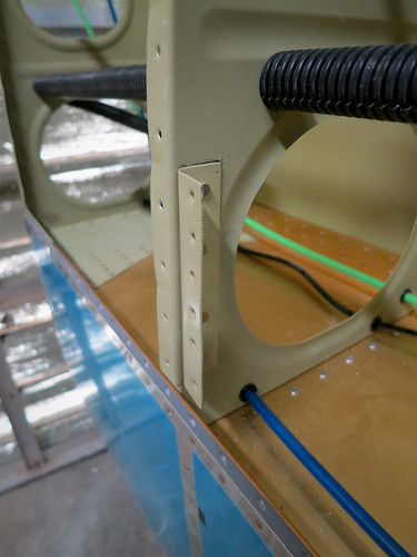
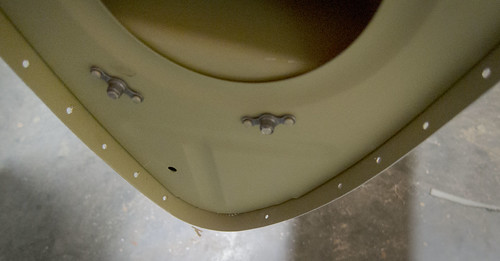
The remainder of the day's work focused on the theme of preparing for the bottom skin on the left wing. I realized after my last entry at the end of March that there were still a few small tasks that needed doing before the bottom skin was on. First was some work on the pitot tube mount. The bracket that attaches the doubler to the rib was ready to be riveted in on the rib side, so I went ahead and did that. Here's a picture of it installed:
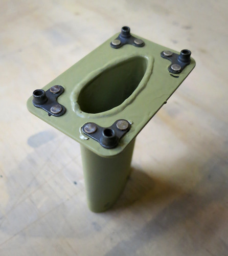
Then I riveted on the nutplates that sit on the top of the pitot mast and are used to attach the skin, doubler, spacer, and mast together. Here's what they look like:
And just for kicks, I stuck the mast, spacer, and doubler in place on the bracket and clecoed them in just to see what it would all look like.
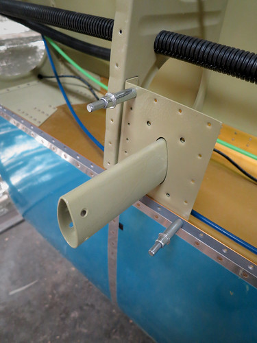
The mast, spacer, and clecos will have to come out of there before I can put the bottom skin on, but the doubler gets riveted in place along with the skin so it's where it needs to be from now on.
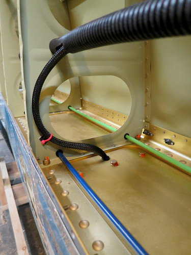
The next bit to take care of that had to be done prior to riveting on the bottom skin was to tend the cable bunding coming through the main spar from the leading edge. I already had it encased in a protective sleave, so I cut a hole in the main wiring conduit and fed the bundle through to the wing root.
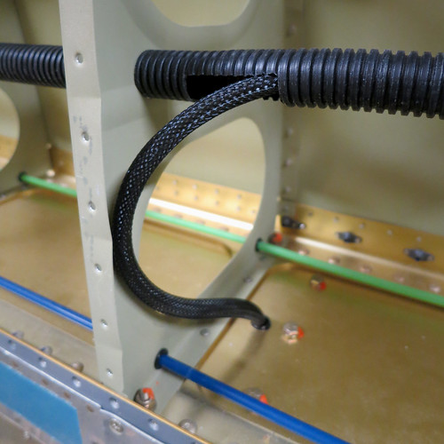
I left the curve in the bundle for two reasons. The first was to ease the transition in direction going into the conduit, the second was to clear the way for the aileron pushrod which needs to move back and forth in the largest lightening hole seen above. I'll probably put a little adhesive wire tie anchor on the face of the rib where the bundle meets it at its lowest point (left-most in this photo) and secure it there. However, to keep it out of the way for riveting on the skin, I'll likely add the wire tie after the skin is already riveted down. The bay one inboard from this one has an access panel that should make this feasible.
The last task prior to adding bottom skins was to cut another hole in the conduit to service the aileron trim servo wiring. This is in the same bay as the inner-most inspection panel and looks just like the hole I cut in the photo above. With that complete, I'm ready to rivet on some skin. Just need to get a helper over to buck, and that's scheduled for tomorrow evening.
9 Jun 2014
Will came by tonight to have a look at the progress on the left wing and help bang out some rivets on the inboard bottom skin. We managed to complete all of the easily-accessible rivets on the aft half the skin. After confirming that neither of us could get a buckingbar up to the rear spar inside one of the narrow wing-walk bays (our fists are wider than the space available), we called it a night.
10 Jun 2014
Yesterday I showed Will what I was thinking for installing the pitot tube and the plumbing behind it and he expressed some concern that having the somewhat massive tubing adapters suspending out in open space supported by soft aluminum tubing was a recipe for tubing failure. He recommended that I connect the adapters to structure somewhere/somehow. I spent some time deciding how best to accomplish this, and today I implemented my solution.
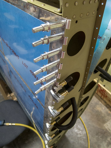
The first step was to shorten the aluminum tubes coming out of the pitot tube to the point that the adapters would just barely be above the mast. After cutting and re-flanging the tubes and re-installing the adapters, I set about building a small custom bracket that would rivet onto the top of the mast base and to which the adapters could be secured with adel clamps. Here's a photo showing the final parts separate and assembled:
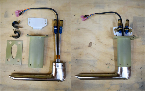
Once those adel clamps are tightened down, there will be no movement in the aluminum tubing at all even in a high-turbulence environment. The clamps have to be removed to get the pitot tube in and out of the mast, which means that for final assembly once the bottom wing skin is on, I'll have to attach the clamps through the wing rib lightening holes from the outboard end of the wing, which will be a pain. But unless something goes terribly awry, I should only ever have to do that once.
With the new plumbing layout above the pitot tube, the plastic airlines now leave the adapters heading straight up and need to make a big turn to loop around to the current plumbing run along the aft surface of the main wing spar. I decided that to keep the loops of tubing as secure as possible, I'd loop them around to the outboard side, through the rib's lightening hole, and back around to the existing snap bushings in the base of the rib. To do this, I'd have to make a bracket to keep the tubes (and the heater wiring harnes) safe as it went through the lightening hole. Here's the simple bracket I ginned up:
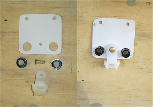
It's just another pair of plastic snap bushings for the air hoses and a wire tie hanger for the wiring bundle. I installed this to the top of the largest lightening hole with a pair of rivets.
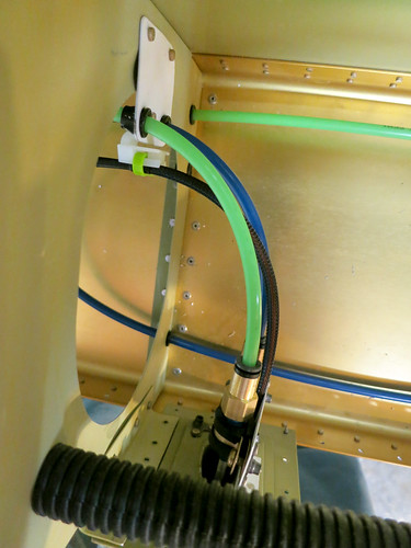
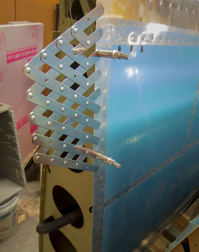
Next, it was time to test-install everything to make sure my solution made sense and that there weren't any engineering details that would bite me and had to be fixed before the bottom skin went on. Here is the view from the bottom of the test install:
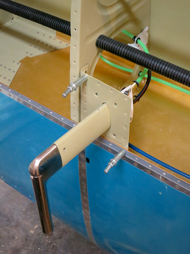
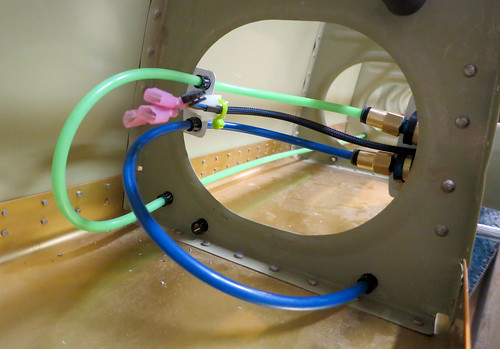
Here's what it looks like from the aft:
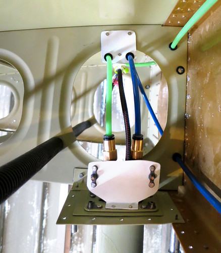
...and from the outboard:
...and from the inboard:
All of the tubing and the wire bundle are kept from rubbing on anything and there is some strain relief on the adapters in case I do something stupid like yank on the tubing from the wing root end during installation of that end. Happy with the installation, I disconnected the tubing from the pitot tube and removed it. It's in storage now until the bottom skin is attached.
15 Jun 2014
Yesterday and today I finished off the left wing's inboard bottom skin. The aft half had already been completed thanks to bucking assistance from Will and Nina. I was able to do all of the forward rivets solo since there is a lot more room to manuever in the wider forward section of each bay. Somewhere in here was the 14,000th rivet in the airplane!
The next thing I did was to go through my list of custom bits on the left wing as well as all of the internal mechanisms, plumbing, and wiring and make sure that there wasn't anything else that needed tending to before I put on the outboard bottom skin. The one item I came across still needing done was to add a wire tie anchor that would keep the stall warning switch wire bundle out of the way of the aileron pushrod. Here's a shot of a test-install of the anchor:
Of course, having the wire bundle over there makes it in the way for getting the bottom skin on, so I took the wire tie back off and pushed the bundle back to the center of the bay. Once the skin is on, I'll re-attach the wire tie (blind, through the access panel that is one bay away). Shouldn't be too painful.
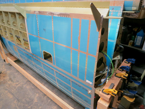
Having confirmed that everything internal to the wing was complete, I went ahead and hung the outboard bottom skin in place--the last piece of skin in the wings! It is ready to be riveted, but that'll have to wait for another day.
22 Jun 2014
Today I started work on the wingtips!
I decided awhile back that I wanted to use the hinge method of attachment for the wingtips rather than the stock screws and nutplates. For one thing, it looks better when it's done. Also, it makes removing the wingtips relatively quick and painless. My advisors have told me many times that if an inspection is difficult to do, then it won't happen nearly as often as it should. So I want to make getting into the internals of the plane as easy as possible. Plus, I've got a fair amount of gear planned to be mounted in the wingtips (APRS controller, pitot heat controller, NAV antenna, marker antenna, NAV lights, strobes, access to the landing lights, possibly landing lights, possibly a camera mount...) so if there's any issues with any of it, I'll need to be able to get the wingtips on and off, preferrably with minimal hassle.
There are lots of great walk-throughs for doing the hinge attachment on the web, but I couldn't find any specifically tailored to the RV-10 and none that also involved the Bob Archer NAV antenna installation. There are also some improvements to the method that I've found in some descriptions and not in others. I'm going to try to make this section as detailed as possible for any future builders that want to go down this path.
The first step was to define a rivet hole pattern in the wing skins for attachment of the inboard half of the hinge. For this, I used a rivet spacer like the one pictured here:
As you can see from the photograph, the rivet spacer makes it easy to make holes that line up with the existing rivets for the outboard rib. The stock holes for the wingtip (seen below the spacer in the photo) are only half as numerous as the rib rivets. I wanted holes for the hinge that lined up exactly with the rib holes next to them. In most cases, this just meant putting evenly-spaced holes between each pair of existing holes. However, around the rear spar, the J-stiffener, the main spar, etc. there were oddly-spaced rivets. I went ahead and duplicated the odd spacing using the rivet spacer tool in order to maintain a professional look. I also added two holes evenly-spaced between the rear spar and the gap fairing rivet lines.
At the nose end, the hinge does not go all the way to the front in order to avoid strong curvature. It took some trial and error to determine how far the hinges should do, and here are the results: a 41.5" hinge on the bottom skin will go from the aft edge of the skin to the forward-most existing hole and not encounter any significant curvature. For the top skin, a 44" hinge will go from the aft edge of the skin to just forward of the second-forward-most of the stock holes. This means that when I was adding holes for the top skin, I did not add a hole between the two forward-most existing holes. Here's a photo of the nose area of the right wing for reference:
The lone forward-most hole on the top skin will not be used and will get filled in later.
Once I had measured and marked the hinges, I removed the pin and snipped them to length with metal snips. This left a sharp edge, which I buffed down with a scotchbrite wheel. Next, I had to choose which half of each hinge would be the inboard half. It is important that the inboard half of the hinge have an eye at the aft end, not a space. Once the hinge halves were marked, I took the inboard halves and clamped them in place, being sure to keep the aft edge flush with the aft edge of the wing skin and the inboard edge flush against the outboard wing rib. Here's a picture of the bottom hinge being match-drilled:
The technique here was nothing special; I just kept the hinge half clamped firmly in place and drilled through the skin into the hinge, adding a cleco for each hole as they were drilled. Clamps were discarded as I reached them. Drilling out both top and bottom inboard hinge halves went very quickly. The skins and hinges were deburred afterwards.
I can't rivet the hinges to the wing skin yet. There needs to be a spacer between the inboard hinge and the skin since the wingtip fiberglass is considerably thicker than the skin aluminum. Several writeups on how to make this spacer suggest using 0.040" aluminum shims, but there is a better method that requires nothing not already in-hand. The wingtip comes with an attachment flange that is thinner than the rest of the wingtip by the thickness of the skin. This flange is normally cut off and discarded when using hinges to attach the wingtips. However, the flange is exactly the right thickness to offset the inboard hinge half. So the basic plan of attack is to trim the wingtip with a 1/2" flange as if you were going to attach it conventionally, then trim the flange and use that as a spacer between the inboard hinge halves and the skin. Even better, the holes can be transferred into the spacer while the flange is still attached to the wingtip, and then the whole hinge used to make holes between the outboard hinge half and the wingtip without having to drill blind through a back-lit piece of fiberglass. All of that I will describe in better detail, with pictures, as I progress through this process.
My apologies, loyal readers... I have taken a couple of months off from the RV-10 in order to concentrate on bird photography during spring migration. But I'm back!
The first thing I did today was a tiny bit of get-ahead work on the wing tips, in which I went ahead and did the surface prep on the only stock metal pieces in the wing tips-the support brackets at the inner trailing edge. This allowed me to start drying out my stock of alumiprep and alodine because I don't like having 20 gallons of toxic acids in my shop when I won't be doing any more sheet metal for awhile.
The remainder of the day's work focused on the theme of preparing for the bottom skin on the left wing. I realized after my last entry at the end of March that there were still a few small tasks that needed doing before the bottom skin was on. First was some work on the pitot tube mount. The bracket that attaches the doubler to the rib was ready to be riveted in on the rib side, so I went ahead and did that. Here's a picture of it installed:
Then I riveted on the nutplates that sit on the top of the pitot mast and are used to attach the skin, doubler, spacer, and mast together. Here's what they look like:
And just for kicks, I stuck the mast, spacer, and doubler in place on the bracket and clecoed them in just to see what it would all look like.
The mast, spacer, and clecos will have to come out of there before I can put the bottom skin on, but the doubler gets riveted in place along with the skin so it's where it needs to be from now on.
The next bit to take care of that had to be done prior to riveting on the bottom skin was to tend the cable bunding coming through the main spar from the leading edge. I already had it encased in a protective sleave, so I cut a hole in the main wiring conduit and fed the bundle through to the wing root.
I left the curve in the bundle for two reasons. The first was to ease the transition in direction going into the conduit, the second was to clear the way for the aileron pushrod which needs to move back and forth in the largest lightening hole seen above. I'll probably put a little adhesive wire tie anchor on the face of the rib where the bundle meets it at its lowest point (left-most in this photo) and secure it there. However, to keep it out of the way for riveting on the skin, I'll likely add the wire tie after the skin is already riveted down. The bay one inboard from this one has an access panel that should make this feasible.
The last task prior to adding bottom skins was to cut another hole in the conduit to service the aileron trim servo wiring. This is in the same bay as the inner-most inspection panel and looks just like the hole I cut in the photo above. With that complete, I'm ready to rivet on some skin. Just need to get a helper over to buck, and that's scheduled for tomorrow evening.
9 Jun 2014
Will came by tonight to have a look at the progress on the left wing and help bang out some rivets on the inboard bottom skin. We managed to complete all of the easily-accessible rivets on the aft half the skin. After confirming that neither of us could get a buckingbar up to the rear spar inside one of the narrow wing-walk bays (our fists are wider than the space available), we called it a night.
10 Jun 2014
Yesterday I showed Will what I was thinking for installing the pitot tube and the plumbing behind it and he expressed some concern that having the somewhat massive tubing adapters suspending out in open space supported by soft aluminum tubing was a recipe for tubing failure. He recommended that I connect the adapters to structure somewhere/somehow. I spent some time deciding how best to accomplish this, and today I implemented my solution.
The first step was to shorten the aluminum tubes coming out of the pitot tube to the point that the adapters would just barely be above the mast. After cutting and re-flanging the tubes and re-installing the adapters, I set about building a small custom bracket that would rivet onto the top of the mast base and to which the adapters could be secured with adel clamps. Here's a photo showing the final parts separate and assembled:
Once those adel clamps are tightened down, there will be no movement in the aluminum tubing at all even in a high-turbulence environment. The clamps have to be removed to get the pitot tube in and out of the mast, which means that for final assembly once the bottom wing skin is on, I'll have to attach the clamps through the wing rib lightening holes from the outboard end of the wing, which will be a pain. But unless something goes terribly awry, I should only ever have to do that once.
With the new plumbing layout above the pitot tube, the plastic airlines now leave the adapters heading straight up and need to make a big turn to loop around to the current plumbing run along the aft surface of the main wing spar. I decided that to keep the loops of tubing as secure as possible, I'd loop them around to the outboard side, through the rib's lightening hole, and back around to the existing snap bushings in the base of the rib. To do this, I'd have to make a bracket to keep the tubes (and the heater wiring harnes) safe as it went through the lightening hole. Here's the simple bracket I ginned up:
It's just another pair of plastic snap bushings for the air hoses and a wire tie hanger for the wiring bundle. I installed this to the top of the largest lightening hole with a pair of rivets.
Next, it was time to test-install everything to make sure my solution made sense and that there weren't any engineering details that would bite me and had to be fixed before the bottom skin went on. Here is the view from the bottom of the test install:
Here's what it looks like from the aft:
...and from the outboard:
...and from the inboard:
All of the tubing and the wire bundle are kept from rubbing on anything and there is some strain relief on the adapters in case I do something stupid like yank on the tubing from the wing root end during installation of that end. Happy with the installation, I disconnected the tubing from the pitot tube and removed it. It's in storage now until the bottom skin is attached.
15 Jun 2014
Yesterday and today I finished off the left wing's inboard bottom skin. The aft half had already been completed thanks to bucking assistance from Will and Nina. I was able to do all of the forward rivets solo since there is a lot more room to manuever in the wider forward section of each bay. Somewhere in here was the 14,000th rivet in the airplane!
The next thing I did was to go through my list of custom bits on the left wing as well as all of the internal mechanisms, plumbing, and wiring and make sure that there wasn't anything else that needed tending to before I put on the outboard bottom skin. The one item I came across still needing done was to add a wire tie anchor that would keep the stall warning switch wire bundle out of the way of the aileron pushrod. Here's a shot of a test-install of the anchor:
Of course, having the wire bundle over there makes it in the way for getting the bottom skin on, so I took the wire tie back off and pushed the bundle back to the center of the bay. Once the skin is on, I'll re-attach the wire tie (blind, through the access panel that is one bay away). Shouldn't be too painful.
Having confirmed that everything internal to the wing was complete, I went ahead and hung the outboard bottom skin in place--the last piece of skin in the wings! It is ready to be riveted, but that'll have to wait for another day.
22 Jun 2014
Today I started work on the wingtips!
I decided awhile back that I wanted to use the hinge method of attachment for the wingtips rather than the stock screws and nutplates. For one thing, it looks better when it's done. Also, it makes removing the wingtips relatively quick and painless. My advisors have told me many times that if an inspection is difficult to do, then it won't happen nearly as often as it should. So I want to make getting into the internals of the plane as easy as possible. Plus, I've got a fair amount of gear planned to be mounted in the wingtips (APRS controller, pitot heat controller, NAV antenna, marker antenna, NAV lights, strobes, access to the landing lights, possibly landing lights, possibly a camera mount...) so if there's any issues with any of it, I'll need to be able to get the wingtips on and off, preferrably with minimal hassle.
There are lots of great walk-throughs for doing the hinge attachment on the web, but I couldn't find any specifically tailored to the RV-10 and none that also involved the Bob Archer NAV antenna installation. There are also some improvements to the method that I've found in some descriptions and not in others. I'm going to try to make this section as detailed as possible for any future builders that want to go down this path.
The first step was to define a rivet hole pattern in the wing skins for attachment of the inboard half of the hinge. For this, I used a rivet spacer like the one pictured here:
As you can see from the photograph, the rivet spacer makes it easy to make holes that line up with the existing rivets for the outboard rib. The stock holes for the wingtip (seen below the spacer in the photo) are only half as numerous as the rib rivets. I wanted holes for the hinge that lined up exactly with the rib holes next to them. In most cases, this just meant putting evenly-spaced holes between each pair of existing holes. However, around the rear spar, the J-stiffener, the main spar, etc. there were oddly-spaced rivets. I went ahead and duplicated the odd spacing using the rivet spacer tool in order to maintain a professional look. I also added two holes evenly-spaced between the rear spar and the gap fairing rivet lines.
At the nose end, the hinge does not go all the way to the front in order to avoid strong curvature. It took some trial and error to determine how far the hinges should do, and here are the results: a 41.5" hinge on the bottom skin will go from the aft edge of the skin to the forward-most existing hole and not encounter any significant curvature. For the top skin, a 44" hinge will go from the aft edge of the skin to just forward of the second-forward-most of the stock holes. This means that when I was adding holes for the top skin, I did not add a hole between the two forward-most existing holes. Here's a photo of the nose area of the right wing for reference:
The lone forward-most hole on the top skin will not be used and will get filled in later.
Once I had measured and marked the hinges, I removed the pin and snipped them to length with metal snips. This left a sharp edge, which I buffed down with a scotchbrite wheel. Next, I had to choose which half of each hinge would be the inboard half. It is important that the inboard half of the hinge have an eye at the aft end, not a space. Once the hinge halves were marked, I took the inboard halves and clamped them in place, being sure to keep the aft edge flush with the aft edge of the wing skin and the inboard edge flush against the outboard wing rib. Here's a picture of the bottom hinge being match-drilled:
The technique here was nothing special; I just kept the hinge half clamped firmly in place and drilled through the skin into the hinge, adding a cleco for each hole as they were drilled. Clamps were discarded as I reached them. Drilling out both top and bottom inboard hinge halves went very quickly. The skins and hinges were deburred afterwards.
I can't rivet the hinges to the wing skin yet. There needs to be a spacer between the inboard hinge and the skin since the wingtip fiberglass is considerably thicker than the skin aluminum. Several writeups on how to make this spacer suggest using 0.040" aluminum shims, but there is a better method that requires nothing not already in-hand. The wingtip comes with an attachment flange that is thinner than the rest of the wingtip by the thickness of the skin. This flange is normally cut off and discarded when using hinges to attach the wingtips. However, the flange is exactly the right thickness to offset the inboard hinge half. So the basic plan of attack is to trim the wingtip with a 1/2" flange as if you were going to attach it conventionally, then trim the flange and use that as a spacer between the inboard hinge halves and the skin. Even better, the holes can be transferred into the spacer while the flange is still attached to the wingtip, and then the whole hinge used to make holes between the outboard hinge half and the wingtip without having to drill blind through a back-lit piece of fiberglass. All of that I will describe in better detail, with pictures, as I progress through this process.
| <-- March 2014 | July 2014 --> |