
| Workshop | Empennage | Wings | Fuselage | Contact |
| <-- October 2009 | December 2009 --> |
Chronological Updates, November 2009
2 Nov 2009
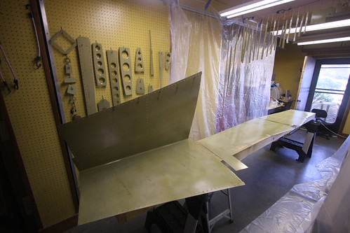
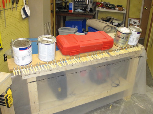
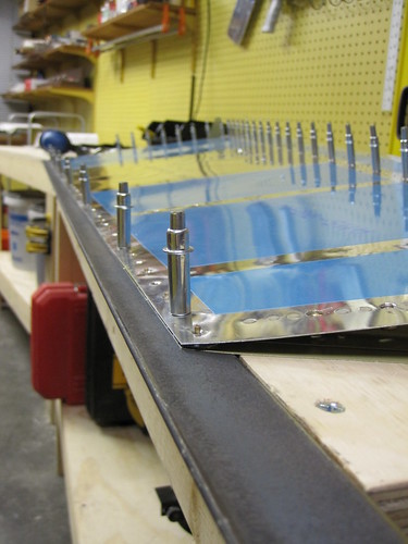
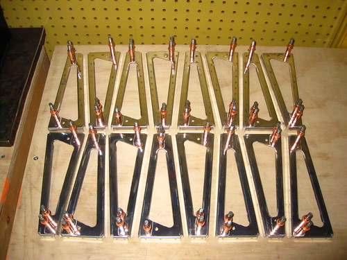
Quite a bit has happened over the past two days. For starters, I primed all of the rudder and vertical stabilizer parts. Riveting together of the vertical stabilizer skeleton has also been started. Here's me about to stat priming all of the non-skin parts.

And here's all of the parts, including the skins, drying after being primed with Akzo 2-part epoxy primer.
Once everything had dried for a few hours, I started in on the vertical stabilizer riveting. The very first rivet in the plane was between the lower rudder hinge bracket and the rudder stop. Unfortunately, I was excited about doing some riveting and failed to follow the instructions; I did all six of these rivets with the second hinge bracket in there too. Not right. Had to drill them all out and start over. Whoops! Once I got past that little snafu, I riveted together the VS rear spar, spar caps, doublers, and rudder hinges. This took a grand total of 75 rivets, almost all of which could be done with the squeezer. The universal rivets that attach the hinges closest to the corner of the hinge have to be done with the rivet gun and bucking bar, and I cleated one of these. Had to drill it out and replace it.
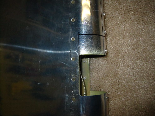
I didn't put on the upper half of the upper hinge bracket, or the upper middle rivet on the upper hinge doubler because I want to replace this rivet with a mounting bolt for a bond strap to run between the VS and the rudder. I'm still having problems figuring out what the right bolt/nut/ring terminal combination is for this, so that bit is on hold. Below is a photo of the upper hinge area showing the unfinished rivets. I also have an AN3-4 bolt there with a castle nut, ring terminal, and some washers there for sacle. The problem with the AN series bolts is that the threaded section is just too short to have a permanently-attached bolt/nut combo and then a removable ring terminal/castle nut combo on top of that. I'm looking for a slightly longer bolt with a shorter grip, and it has to be passivated. So far, no joy.
Tabling the rear VS spar for now, I moved on to the forward VS spar, which needs very little treatment. Just 10 rivets for the doubler—four flush and six universal. I used the squeezer on the universals which was a breeze, and then used my new back riveting plate on the flush which was also quite straightforward. Nina was around while I was doing this, so I showed her how to use both the squeezer and the rivet gun. She did four of the rivets on this part and they all look great.
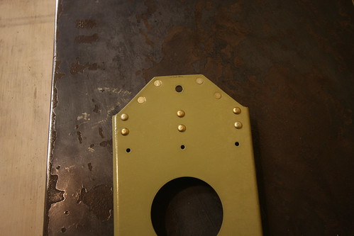
From there, it was time for the customizations to the forward ribs for the wiring and conduit runs. First up was the lower rib, which got a custom doubler plate and the circular plastic connector riveted into the doubler:
Then the top rib doubler and CPC. Here I made a small mistake; I meant to put the doubler on the bottom of the rib, but forgot that this rib gets installed flanges-up. By the time I had noticed, the doubler was already fully riveted into the web. Not a big problem; but you can still read my sharpee'd "bottom" notation on the top of the doubler. No big deal, bit I need to be more careful. Too many mistakes.
Last up was the forward middle rib, which just got two wire tie anchors riveted into the two lightening holes. One will secure the conduit, the other the wire bundle.
I'll probably go ahead and rivet up the rest of the VS skeleton soon since I can still do the grounding post modification after the skeleton is assembled. Riveting on the skin will have to wait for the bolt issue to be resolved, however.
3 Nov 2009
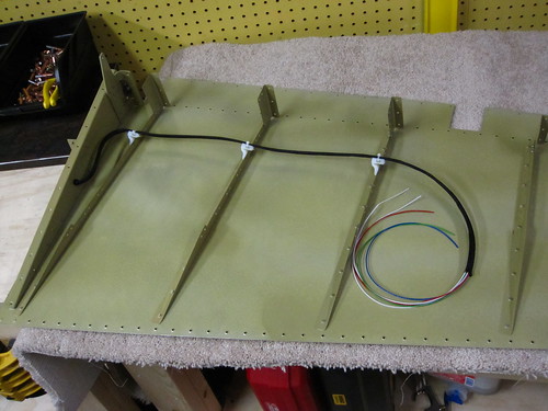
Riveted together the skeleton pieces (except for the lower inspar and forward ribs, as per the instructions). This required only 11 rivets, eight of which could be squeezed, so it went very quickly. The rest of the session was spent routing cables and conduit.
The conduit went very quickly; there's not much to it. Wire tied it to the middle rib anchor point and stuffed it through the two 3/4" holes at the top and bottom.
The wiring was considerably more complex. Each wire has crimped sockets attached to each end, the bundle of nine cables is run through a woven abrasion-resistant sheath, and the ends of the cable have heat shrink strain relief boots attached to them.
The trick was getting the length right. The lower forward rib has to be removed during riveting in order to be able to reach the back side of the middle forward rib for bucking the skin rivets. Once this is done, however, the skin is permanently in place and there is no longer access to the top of the lower forward rib to attach the cables into the connector, etc. What I decided to do was go ahead and pre-attach the conduit and cables, but leave enough slack that the lower rib can be detached and moved slightly out of the way—just long enough that a bucking bar and arm can be stuck up in there. When its time to put the lower rib back in place, I'll just push the slack back into the cavity and rivet the rib in place. The conduit slack can be pulled through and the conduit cut to length. The wire harness, unfortunately, cannot. So that slack will remain. I arranged the harness such that the preferential bend in the bundle will push it out towards the leading edge of the skin rather than the forward spar, whose lightening holes could pose an abrasion risk.
6 Nov 2009
A couple of days ago I borrowed a heat gun and some RTV from Bob and finished off the wiring installs in the vertical stabilizer. The VS is now awaiting the grounding studs that are scheduled to arrive on Monday before I can start putting the skins on.
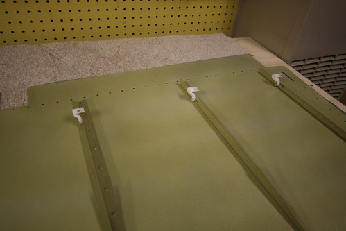
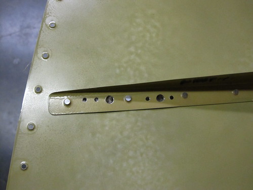
Tonight, in lieu of anything to do for the vertical stabilizer, I started the riveting steps on the rudder. The two spar doublers that suppor the hinge attach nutplates were the easiest. Everything could be squeezed and there were no problems. Here's the aft side of the upper doubler.
I need to add a ground post here as well, to be the counterpart to the one I'm adding to the VS. Since there was so much open space on this doubler, I figured I'd go ahead and rivet all existing holes and just add a hole between the two upper rivets for the post hardware. That step is now on hold awaiting the grounding studs arriving on Monday.
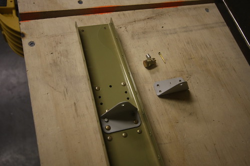
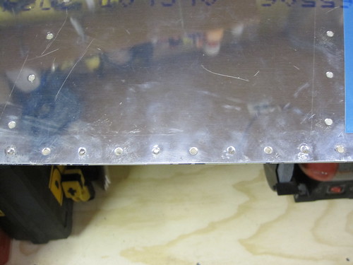
Riveted together the components of the bottom rudder rib, including the horn and the wiring customizations I made. This consists of a plastic bushing going through the rib to allow access to the interior of the rudder for the rudder trim wiring.
Here's a view of the bottom side of the completed lower rudder rib:
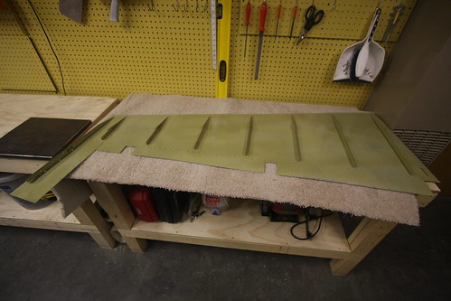
After that, the next step is to start back riveting the stiffeners onto the rudder skins. This went great, for awhile. I got awesome-looking rivets:
...and then I screwed it up really badly. I started going too quickly and didn't pay attention to where my steel plate was beneath the skin. I attempted to back rivet a rivet that was just barely off the edge of the plate. This achieved several very bad things in very short order. For starters, the skin got creased over the edge of the steel plate and is now decidedly unflat in the area of the rivet. The rivet hole is deformed and will require drilling out to a larger size. Finally, the edge of the back rivet set caught the edge of the steel plate, bending the spring collar and causing the moving parts of the rivet set to jam. That'll have to be replaced. Great.
Not sure if I can use this skin at all, now. My first impression is that the integrity of the skin is not compromised; it'll just look bad. I'm going to pass it by some other builders and see what they think before I proceed.
12 Nov 2009
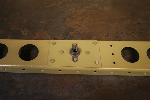
Yesterday over lunch I spent an hour and got the bond strap attachement stud attached to the top end of the vertical stabilizer rear spar.
This involved several steps. First, I test-fit the stud and its attachment hardware (including the ring terminal and castle nut). I used a sharpee to mark the footprint of the washers on the spar and doubler so that I'd know where to remove the primer coating. Also marked the appropriate place for a cotter pin hole in the castle nut. All hardware was removed and a Dremel drum sander was used to rip off the primer from where the washers will contact the spar and doubler. This should make for an excellent electrical connection.
Next, all of the aft-side hardware was attached to the threaded rod stud and placed into the hole. A bead of red threadlocker was added to the forward side of the stud and the forward-side hardware tightened down into place. The aft-side hardware was then removed, threadlocker added to this side, and the permanent hardware was tightened back into place. When the threadlocker cures (24 hours), the bonding stud will be permanently in place. I went ahead and added a generous blob of epoxy gel to the foreward side to further hold everything in place. On the aft-side, where the strap ring terminal will attach, I had to be more judicious with the epoxy. I just added enough to cover the exposed aluminum under the washer and add some additional locking to the nut. The top surface of the nut was kept clear of epoxy since this is the electrical bond surface for the strap hardware.
With the bond stud in place, it was finally time to add the skin to the vetical stabilizer. Initially, this just involved clecoing the skin in place. I went ahead and detached the lower nose rib so that the initial rivets in the middle nose rib could be bucked.
Today over lunch, Bob came down and we spent an hour doing rivets. This was Bob's first experience with riveting, and the first rivets to do on that middle nose rib are probably some of the most akward and difficult rivets in the whole plane. But he was very good with the bucking and we managed to get all three nose ribs completed and looking good.
There were a couple small mistakes, minor smilies, etc, but nothing that I'm concerned about. One of them is below the empennage fairing line and the other is small enough that I think a bit of filler will cover it when it comes time to paint.
14 Nov 2009
Yesterday I added the 32 small universal rivets connecting the vertical stabilizer rear spar flanges to the spar caps below the skin. These were straightforward as they can all be squeezed, though I managed to get a few where the head wasn't seated all the way down correctly. The difficulty is that with the pneumatic squeezer and the geometry of the piece, the cupped head of the rivet has to go on the moving part of the squeezer. Thus, as the squeezer is engaged, the entire device has to move relative to the spar flange, rather than the squeezer staying put and just the flush end ramming into the back of the rivet. If this movement isn't conducted just right, the rivet can be pushed out of position a bit before the two ends of the squeezer start applying equal force, resulting in a poorly-seated rivet. I haven't figured out the solution to this yet. For now, I have a few rivets that need to be drilled and re-done.
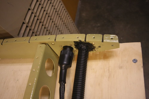
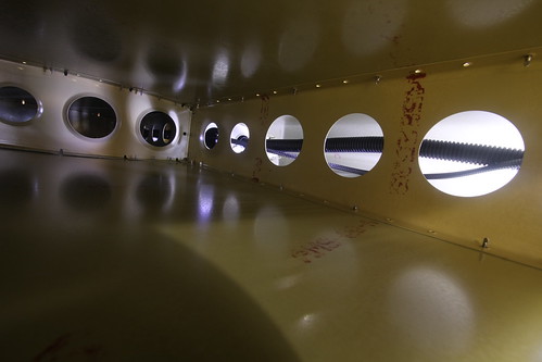
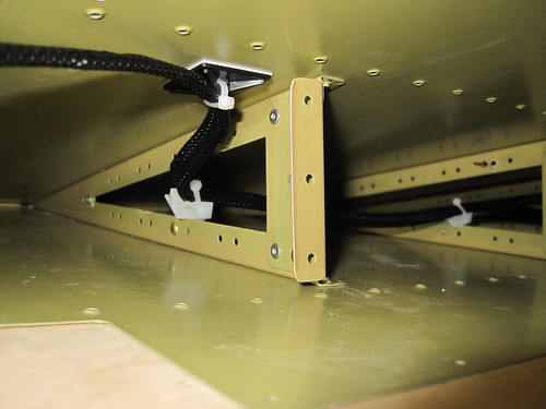
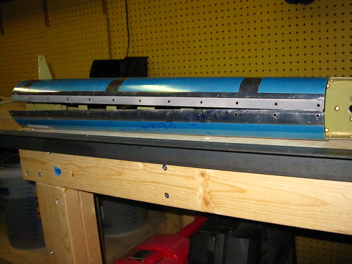
While waiting for assistance to buck the rest of the skin rivets, I pulled the slack out of the wiring conduit, preventing it from rubbing against anything inside the plane. I put some black RTV on a gloved finger and stuck it through the forward-most lightening hole of the lower nose rib so that I could make a vibration-cancelling fillet where the conduit passes through the doubler, but not visible from the outside. Here is a picture of the inside of the vertical stabilizer. The wire bundle and conduit in the lower-front cavity can be seen through the lightening holes:
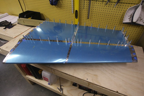
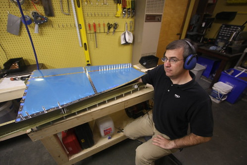
Last night, Bob came by with a pizza and we did Dinner & Rivets (soon to be a recurring feature, I hope). Bob acted as the bucking bar placement specialist as we drove the final 218 rivets into the skin. Here he is during the cumbersome bucking of the upper forward spar rivets, which require pealing back the skin a bit and wedging your arm inside.
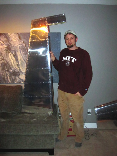
After about three hours of work, the vertical stabilizer was done! (at least as far as Section 6 of the plans is concerned...)

I'm pretty happy with how it turned out. We went through and examined every visible rivet and marked seven that needed to be replaced because they weren't seated correctly. There are a handfull of smilies and small deformities in the skin from one mistake or another, but nothing that raises a safety concern. I think most of them will be magically whisked away when I give it a once-over with filler prior to priming. Remaining tasks for the vertical stabilizer are now:
15 Nov 2009
Spent a few hours this afternoon getting some of the rudder parts riveted together. This had been on hold ever since I broke my back-rivet set last week. A replacement came in the mail on Friday and today I put it to use.
With all of the stiffeners attached to the skins, I moved on to the wire tie anchors needed to securely route wires from the lower fairing up to the rudder trim servo. These were the same anchor parts I used to pass wires and conduit through the lightening holes in the vertical stabilizer. In retrospect, I put them on the wrong side. I attached them to the left-side skin because that's what I had on the bench at the time. However, the right-side skin is where the rudder horn and lower rib get attached before the two sides are sewn up. If I had put them on the right side, I could run the entire wire bundle before beginning the pro-seal attachment activities (which are going to be hectic enough as it is with its limited pot life). Now, I'll have to do the wire-tieing as I go during the pro-seal ordeal.
Next I attached the rudder horn and lower rib to the right-side skin. This involved using the squeezer and the rivets came out very well. The only difficulty was the forward-most rivet, which the pneumatic squeezer can't reach. I'm not sure how to proceed on that one. With the body of the squeezer on the outside of the skin, the squeezer runs into the rudder horn. With the body of the squeezer on the inside of the skin, it runs into the opposite flange. I can't back-rivet it because the rivet gun will also run into the opposite flange. I can't use an offset set because they're all cupped. Have to think about this one. Perhaps someone makes an offset flush set?
With the horn attached (with all but one rivet), I went ahead and blind riveted the shear clips on. This was my first experience with blind rivets; they're really easy and fun to watch. It's a shame they aren't flush or structural.
16 Nov 2009
With where I left off last night, the rudder is now at the point in the instructions where the next step is to rivet the two sides together, rendering the insides largely inaccessible. With that in mind, it was time to take care of the internal customizations.
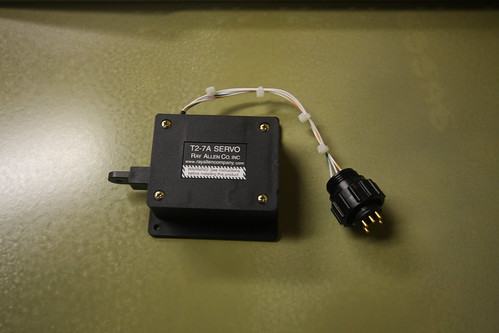
The first thing I did was put a circular plastic connector on the rudder trim servo wires. These are tiny 26awg wires which I had to buy special crimp pins for. The connector came out very well.
I was going to do the wiring harness that connects this CPC to the one riveted to the bottom of the lower rudder rib, but realized that I had neglected to get sockets appropriately sized for the 20awg wires I recently purchased for this harness. I went ahead and ordered the necessary parts (from mouser.com, of course) and the wiring harness will have to wait.
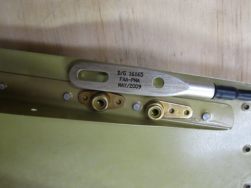
I also took a look at the static wick attachment options. There's going to have to be some rivet surgery; I should have thought about this before I riveted on the upper stiffeners. Each of the two wicks will need to have two nutplates installed on the left skin. The holes in the Dayton Granger 16165 wicks are sized for a #10 screw, so I ordered some AN525-10R6 and AN525-10R7 washer head screws from Aircraft Spruce in addition to some anchor nuts with elastic inserts. If I can fit these nutplates inside the very narrow trailing edge of the rudder, then my wicks will be removeable with a simple screwdriver when required for replacement or aesthetic snobbery. However, until this hardware shows up, the wicks are on hold as well.
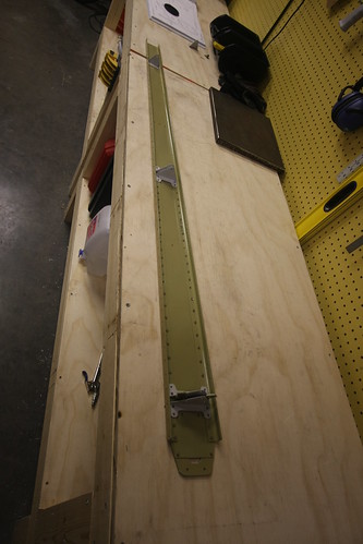
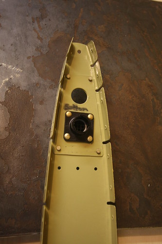
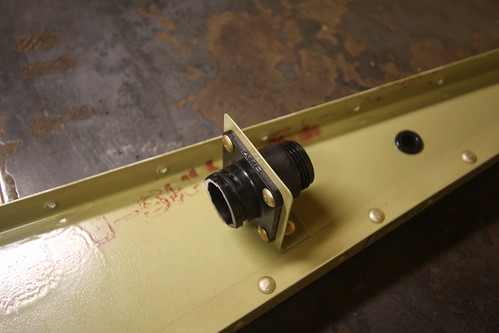
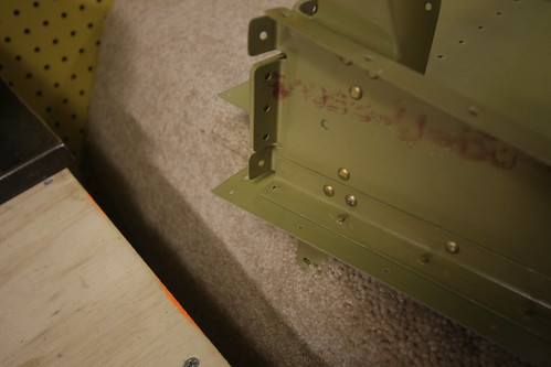
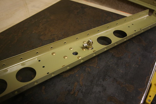
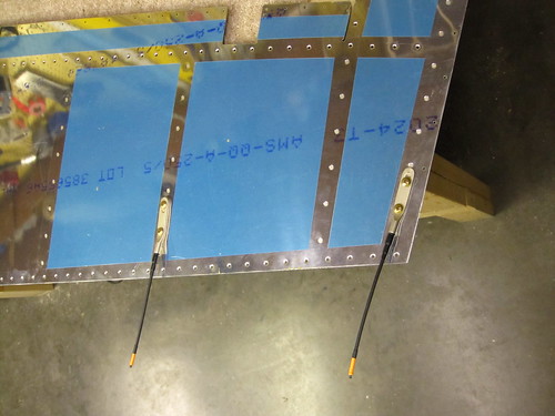
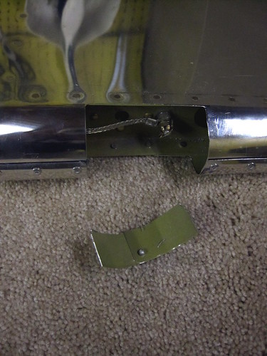
What I did have hardware for was the rudder bonding stud— the counterpart to the one I installed in the vertical stabilizer rear spar last week. This one is a clone of the VS stud and was prepared and installed in basically the same way. Here's a shot showing where I put it:
Unlike the VS stud, this one did not take the place of a rivet; I simply made a new 3/16" hole in between the upper most rivets on the doubler for the upper hinge nutplate on the rudder spar. On a whim, I measured the resistance between the top of the bonding stud and one of the adjacent rivets. It was 0.2 Ohms. From the top of the stud to the far end of the rudder spar was 4 Ohms.
19 Nov 2009
Today the pins and sockets which allow me to finish the rudder wiring arrived (along with some oops rivets to fix the two remaining biffed rivets on the VS). I bit the bullet and moved the wire tie anchors over from the left skin to the right. This allows me to pre-wire the rudder trim harness before having to button up the two sides of the rudder.
I stuffed a piece of 3/8" braided sheath through the snap bushing in the lower rudder rib, then fed the five 20awg wires through. The sheath was then wire-tied to the wire tie anchors in such a way that the sheath never touches metal anywhere (except on the free end, for now).
I put CPC pins on the lower end of each and fed them into the CPC that had been riveted into place when I fabricated the lower rib.
The upper end I am leaving unfinished until the time comes to actually wire up the servo. There will be an access plate cut into the left-side skin for getting at the servo, and through this hole I can finish the connector on the other end of this harness. In the meantime, I applied a pair of adhesive wire-tie anchors to the inside of the left-side skin, just aft of the spar. I'll tied the wires in place with these, keeping them out of the way for the final assembly of the rudder. When the time comes to cut rudder modifications into the rudder, I'll free the wires and run them through the lightening holes of the rudder to keep them out of the way.
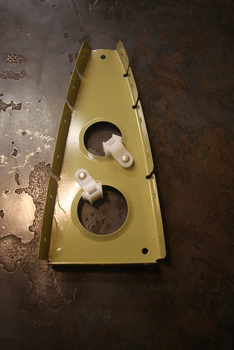
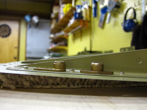
The next task was to figure out how to attach the static wicks. I purchased some one- and two-lug anchor nuts with elastic inserts sized for a #10-32 thread. The #10 fits perfectly through the holes in the Dayton-Granger 16165 static wicks. Aircraft Spruce sells an AN525-10R7 washer-head screw that matches the #10-32 thread, has a head perfectly sized to hold the static wick down, and is exactly the right length so that the last thread protrudes out of the elastic insert but no further. This will allow me to put the nutplates as far aft as possible, where space comes at a premium. Here is an overhead view of the two nutplates I intend to use for the upper static wick just sitting in place and a wick next to them:
And here is the side view of the same anchor nuts showing how they fit within the rudder headroom next to the stiffener angle:
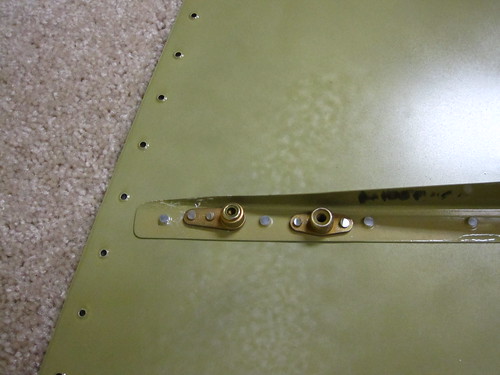
Note that these tests were done on the right-side skin because its stiffener was slightly taller at this end and was a more accurate representation of the available headroom. The wicks will actually be attached to the left-side skin, however, to add to the right rudder effect.
The next task will be to drill out the holes for the anchor nuts and countersink the rivet holes on the outside, allowing for AN4263-4 flush rivets to be back-riveted in.
22 Nov 2009
A couple days ago I finished up work on the rudder static wicks. First I drilled the holes out for the nutplates. I learned the hard way that the right order to do these in is to drill the large hole first, then attach the nutplate with a bolt and use the nutplate as a template for the two rivet holes. Trying to drill the smaller holes first, cleco them in, and then drill through the threaded part of the nutplate proved infeasible and I ended up having to enlarge the larger holes on one of the wick emplacements. Big holes first.
With the holes drilled and deburred, I set about countersinking the rivet holes on the outer side. They have to be flush because the flat static wick surface lays right across the top of them. Unfortunately, the skin is quite thin and the stiffener isn't exactly thick, either. Furthermore, with the stiffeners already in place, there wasn't a good way to get the holes level under my drill press. So I countersunk manually using my deburring tool. The countersinks aren't perfectly circular, but you have to get really close and be looking for it to notice that. I was able to back-rivet all of the rivets, except the spring sheath on my new back rivet set is made of poly instead of metal so it has to be thicker. The rivets adjacent to the threaded part of the anchor nuts ended up cleating a bit because the thicker sheath prevented the set from making full contact. This would be one advantage to the Isham Inc. backrivet set (the one I broke); it wouldn't have had this problem. I didn't worry too much about the cleated rivets, though, since these aren't structural and once the wicks are screwed in, they're redundant entirely.
With the anchor nuts attached, the static wicks screw right on from the outside. They're replaceable if needed, and removable if I want the plane to have cleaner lines for a photo op or something. Very happy with how this turned out.
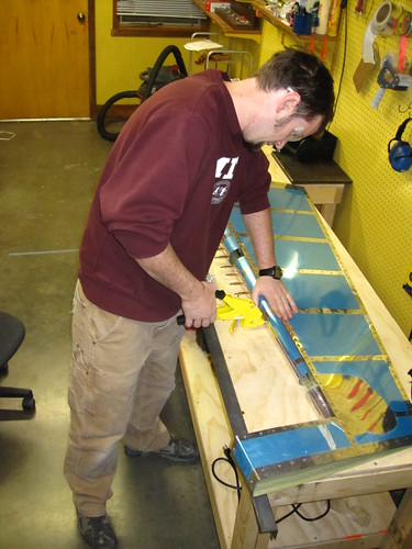
Today, Bob came down and we spent a couple hours dealing with the first dreaded task of the entire plane: the rudder trailing edge. This, of course, involves the first usage of ProSeal (or its equivalent that Van's sold me) on the aircraft. This is nasty stuff; it sticks to everything and smells pretty bad to boot. I went through four pairs of nitrile gloves in a bit over an hour. I used a little hard plastic squeegee to apply the sealant to the extruded aluminum piece. Here's what it looked like once I got both sides applied and the edge piece layed on the skin.
Getting clecos to stay in the trailing edge holes proved to be really difficult. Certain holes just seemed to be slightly oversized from the dimpling or something and wouldn't hold a cleco. Others would hold a cleco in one orientation but not if it twisted. Others would hold some clecos but not others.
Bob held the skin back while I did all the internal blind rivets and added clecos to the trailing edge. I tied the rudder trim wire bundle to an adhesive wire tie anchor on the left skin to keep it out of the way of this process.
In the end, with the two skins attached via the stiffeners and the sealant, I was only able to get about 85% of the clecos into the trailing edge to stay.
I put a board on top of the skin to weigh it down and put some heavy stuff on top of that, but with all the missing clecos there were still some places where the trailing edges weren't as tight as I'd like. So Bob and I made a 9:30pm run to the grocery store and picked up 100 clothes pins for $4. They were small ones without a lot of clamping force, so I didn't have to worry about denting the aluminum or anything like that. But it was enough to bring the trailing edge skins down onto the extruded aluminum piece everywhere. We used a ton just to be safe:
Now I wait for two days while the sealant cures. This is convenient, because this is Thanksgiving week coming up and I have Wednesday, Thursday, and Friday off. So two day week, and a two day pause required for curing. As soon as my vacation rolls around, I'll be ready to work again (though my first cross country flight training is Wednesday morning, so the rudder work will be delayed a bit by that).
26 Nov 2009
Happy Thanksgiving. Before (and after) doing The Meal™, I got some work done on the rudder.
I didn't have an assistant to help me with bucked rivets, so I tried to do everything I could that involved blind rivets first. This began with the connections between the rudder spar and the shear clips. However, before I did those I wanted to do some final tending on the rudder trim wire harness. I put a final wire tie into one of the adhesive anchors on the inside of the left-side skin.
Then I put the spar in place and routed the wire harness through the nearest lightening hole. The idea is that the wire harness will be out of the rudder trim bay when I go to make the cuts for the access panel and the trim tab itself. For the time being, I'll just run the wires down the forward side of the spar, between the spar and the rounded leading edge. Once the cuts are made in the trim area, I'll pull the wire harness back through the lightening hole and tend the end. With the wiring taken care of (for now), the spar's blind rivets went really quickly.
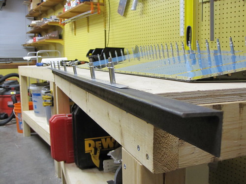
With that, the only remaining task on the rudder that I could accomplish without an assistant was riveting the trailing edge. I had been somewhat apprehensive about starting this because there's a lot of talk on builder's logs about it being 1) difficult and 2) critical. I decided to go with a variation of the method described on Tim Olson's website—to make a long back-rivet plate out of a 6' piece of 2"x2" angle iron and cleco the rudder to it.
I started by screwing the angle iron into my work bench such that the top surfaces of both were flush. Then I used the elevator trailing edge extrusion as a template to drill holes into the top surface of the angle iron. I drilled every 10th hole plus one at the end so that there would be clecos at each end of the rudder, for a total of 7 clecos holding the rudder onto the plate.
With the holes in place, I put rivets into every other hole of the trailing edge, secured them with rivet tape, then flipped the rudder over and attached it to the angle iron with clecos.
I just used a flush set on the shop side of the rivets and they came out OK. With the first side's rivets complete, I removed the clecos, put rivets in the remaining holes (with the exception of the seven cleco holes), taped them, flipped the rudder over, and back-riveted these new rivets. This left just the seven holes to be done without the aid of cleco attachment to the back-rivet plate. This was not a problem and they didn't introduce any bend to the trailing edge.
All-in-all, the trailing edge was exceptionally easy with this method and I got a great-looking, unwavy, un-bend trailing edge out of it. Highly recommended for future builders.
28 Nov 2009
Big day for the rudder.
Nina gave me a hand in the morning bucking the rivets connecting the skins to the rudder spar. We also finished off the lower rib flange rivets and the rivets attaching the two halves of the upper rib. With that, it was time to do the rudder counterweight.
The lead weight was clamped into place and the skins bent around it by hand. After that, a bending jig was assembled out of blocks of wood and C-clamps.
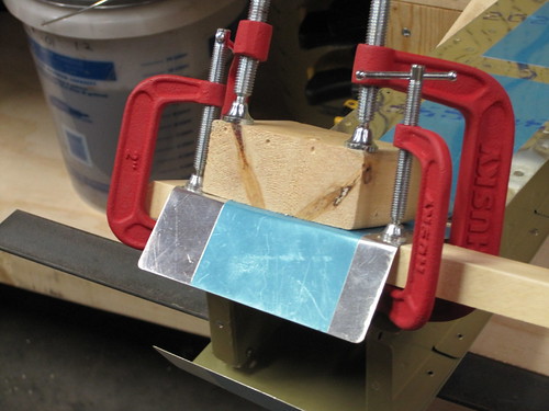
From there, the skins are bent into tight angles so that they will envelope the lead brick. Before inserting the lead brick, I added a couple of small customizations not given in the plans. First, I covered the lead brick's edges in a ring of electrical tape so that there will be no exposed lead in the final part.
The other minor change was to prime the piece of skin that is covered by the other side skin on the forward side of the lead brick. I scuffed this area with scotchbrite then used a Krylon spraycan primer.
Once these modifications were made, the lead brick was attached to the rudder permanently.
With the counterweight complete, it was time to close up the leading edge of the skins. However, before this was done I had to attach the bonding strap to the my custom bonding stud. This was a straightforward crimp of the strap into a ring terminal, and adding a castle nut and cotter pin to hold it in place.
The leading edge skin tabs were rolled using a 1" diameter broom handle. The section of the skin that gets overlapped was again treated with primer, just as was done for the counterweight skins.
Once all the match drilling and priming was complete, the leading edge was cleco'd up again and then the blind rivets were put in place. This is a quick operation.
With that, the rudder as specified in Section 7 of the plans was complete.
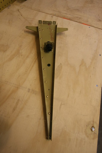
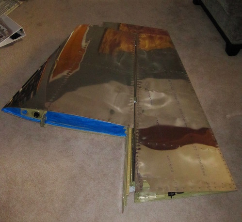
I placed the rudder down next to the vertical stabilizer to check the fit. Unfortunately, the VS bonding stud runs into the leading edge curve of the rudder. I'll have to cut off a bit of the upper leading edge of the rudder to make room for this, but that's not a terribly difficult modification.
Of course I haven't made the mechanical modifications for the rudder trim system either. This will be a major undertaking and entirely off the reservation as far as the plans are concern. However, I do not need to make this modification immediately; I'll probably save it for some time when I'm waiting for a future kit to ship or for more money to be made so that I can buy the next kit. Rudder trim is to be continued; for now, the rudder is "done."
29 Nov 2009
The first thing I did today was finish up a few remaining tasks on the vertical stabilizer and rudder. The vertical stabilizer just needed a couple of rivets put in. They were at the bottom of the foreward spar and I had biffed them the first time through, then really mangled the holes trying to drill them out. My solution was to get some big 3/16" AN470 rivets to fill the holes. I drilled out the new big holes with my right-angle drill kit, inserted the big fatty rivets, and drove them home with my 3x rivet gun. No problem. Aside from being huge, they look great. They're probably stronger than the original rivet, so as far as I'm concerned its an improvement. I now pronounce the vertical stabilizer complete until Section 12 (fiberglass fairings) comes along. I taped up the holes in the VS to prevent bugs from getting in, and put it out in the shed for long-term storage.
Next I put a few last touches on the rudder. First I cut a small section out of the leading edge above the upper hinge opening to make clearance for the vertical stabilizer's bonding stud.
The cut was made with a dremel cutoff wheel and was straightforward. I cleaned up the edges with a file and an edge deburring tool. As a result of the cut, the rudder's bonding stud is now directly accessible, which may aid in future inspections and maintenance, though the whole point of not having a more compact bonding attachment on the vertical stabilizer was because the rudder attachment would be harder to reach. Now they're both about the same difficulty to work with... so I'm not sure if there would be a better arrangement if the assumption was made up front that this cut would be made.
Something to think about for future builders wanting to do some bond strap work, I suppose. Regardless, I'm happy with how it turned out. The VS and rudder fit together perfectly now.
I taped up the holes in the rudder for the same reason as I had in the VS, and while doing so found three rivets at the base of the rudder spar that I had overlooked yesterday. Whoops! Not a problem, they were still fully accessible so I just squeezed them in and that was that. The rudder is now complete until Section 12 (or until I decide to make the rudder trim cuts, whichever comes first).
Now it's time to move on to the next section. The next section of the plans is the horizontal stabilizer. But because I still have the trailing edge back-rivet plate installed on my workbench and because I don't relish the idea of working with a 12' long assembly, I decided to do the elevators first.
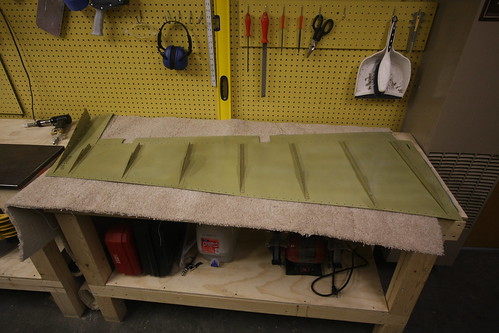
The first step, as with all of the empennage subassemblies, was to do some bandsaw work. I cut apart the rib halves and the shear clips and then deburred everything. Step 2 on the first page of the elevator plans just says "deburr all parts." This step takes a long time. However, once it's complete, the elevators start to take shape remarkably quickly. First up was the ribs:
Next was the tip counterweight assemblies. These took some time because the flanges on the steel pieces didn't line up as well as the aluminum parts I'm used to. Had to use a ton of clecos to get everything to stay in place, too.
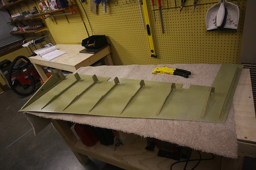
Next I did some drilling on the shear clips and tip assemblies. Then some bends were made to the close out tabs on the four elevator skin sheets. After that, the skeleton starts to come together in short order. The forward and rear spars as well as the ribs all get cleco'd together and to the bottom skins. Suddenly, I had what looked somewhat like elevators on my workbenches.
The next step is a bunch of match drilling, which I didn't feel like doing, so I called it quits here for the day.
Quite a bit has happened over the past two days. For starters, I primed all of the rudder and vertical stabilizer parts. Riveting together of the vertical stabilizer skeleton has also been started. Here's me about to stat priming all of the non-skin parts.
And here's all of the parts, including the skins, drying after being primed with Akzo 2-part epoxy primer.
Once everything had dried for a few hours, I started in on the vertical stabilizer riveting. The very first rivet in the plane was between the lower rudder hinge bracket and the rudder stop. Unfortunately, I was excited about doing some riveting and failed to follow the instructions; I did all six of these rivets with the second hinge bracket in there too. Not right. Had to drill them all out and start over. Whoops! Once I got past that little snafu, I riveted together the VS rear spar, spar caps, doublers, and rudder hinges. This took a grand total of 75 rivets, almost all of which could be done with the squeezer. The universal rivets that attach the hinges closest to the corner of the hinge have to be done with the rivet gun and bucking bar, and I cleated one of these. Had to drill it out and replace it.
I didn't put on the upper half of the upper hinge bracket, or the upper middle rivet on the upper hinge doubler because I want to replace this rivet with a mounting bolt for a bond strap to run between the VS and the rudder. I'm still having problems figuring out what the right bolt/nut/ring terminal combination is for this, so that bit is on hold. Below is a photo of the upper hinge area showing the unfinished rivets. I also have an AN3-4 bolt there with a castle nut, ring terminal, and some washers there for sacle. The problem with the AN series bolts is that the threaded section is just too short to have a permanently-attached bolt/nut combo and then a removable ring terminal/castle nut combo on top of that. I'm looking for a slightly longer bolt with a shorter grip, and it has to be passivated. So far, no joy.
Tabling the rear VS spar for now, I moved on to the forward VS spar, which needs very little treatment. Just 10 rivets for the doubler—four flush and six universal. I used the squeezer on the universals which was a breeze, and then used my new back riveting plate on the flush which was also quite straightforward. Nina was around while I was doing this, so I showed her how to use both the squeezer and the rivet gun. She did four of the rivets on this part and they all look great.
From there, it was time for the customizations to the forward ribs for the wiring and conduit runs. First up was the lower rib, which got a custom doubler plate and the circular plastic connector riveted into the doubler:
Then the top rib doubler and CPC. Here I made a small mistake; I meant to put the doubler on the bottom of the rib, but forgot that this rib gets installed flanges-up. By the time I had noticed, the doubler was already fully riveted into the web. Not a big problem; but you can still read my sharpee'd "bottom" notation on the top of the doubler. No big deal, bit I need to be more careful. Too many mistakes.
Last up was the forward middle rib, which just got two wire tie anchors riveted into the two lightening holes. One will secure the conduit, the other the wire bundle.
I'll probably go ahead and rivet up the rest of the VS skeleton soon since I can still do the grounding post modification after the skeleton is assembled. Riveting on the skin will have to wait for the bolt issue to be resolved, however.
3 Nov 2009
Riveted together the skeleton pieces (except for the lower inspar and forward ribs, as per the instructions). This required only 11 rivets, eight of which could be squeezed, so it went very quickly. The rest of the session was spent routing cables and conduit.
The conduit went very quickly; there's not much to it. Wire tied it to the middle rib anchor point and stuffed it through the two 3/4" holes at the top and bottom.
The wiring was considerably more complex. Each wire has crimped sockets attached to each end, the bundle of nine cables is run through a woven abrasion-resistant sheath, and the ends of the cable have heat shrink strain relief boots attached to them.
The trick was getting the length right. The lower forward rib has to be removed during riveting in order to be able to reach the back side of the middle forward rib for bucking the skin rivets. Once this is done, however, the skin is permanently in place and there is no longer access to the top of the lower forward rib to attach the cables into the connector, etc. What I decided to do was go ahead and pre-attach the conduit and cables, but leave enough slack that the lower rib can be detached and moved slightly out of the way—just long enough that a bucking bar and arm can be stuck up in there. When its time to put the lower rib back in place, I'll just push the slack back into the cavity and rivet the rib in place. The conduit slack can be pulled through and the conduit cut to length. The wire harness, unfortunately, cannot. So that slack will remain. I arranged the harness such that the preferential bend in the bundle will push it out towards the leading edge of the skin rather than the forward spar, whose lightening holes could pose an abrasion risk.
6 Nov 2009
A couple of days ago I borrowed a heat gun and some RTV from Bob and finished off the wiring installs in the vertical stabilizer. The VS is now awaiting the grounding studs that are scheduled to arrive on Monday before I can start putting the skins on.
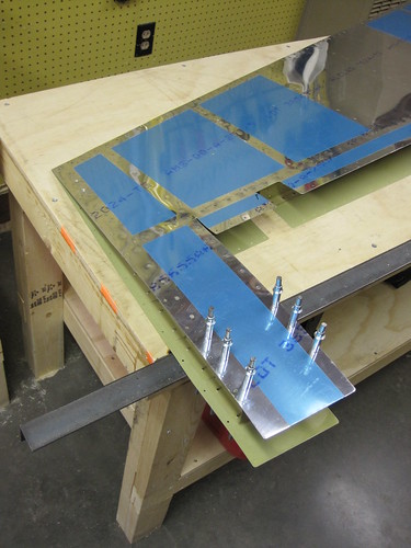
Tonight, in lieu of anything to do for the vertical stabilizer, I started the riveting steps on the rudder. The two spar doublers that suppor the hinge attach nutplates were the easiest. Everything could be squeezed and there were no problems. Here's the aft side of the upper doubler.
I need to add a ground post here as well, to be the counterpart to the one I'm adding to the VS. Since there was so much open space on this doubler, I figured I'd go ahead and rivet all existing holes and just add a hole between the two upper rivets for the post hardware. That step is now on hold awaiting the grounding studs arriving on Monday.
Riveted together the components of the bottom rudder rib, including the horn and the wiring customizations I made. This consists of a plastic bushing going through the rib to allow access to the interior of the rudder for the rudder trim wiring.
Here's a view of the bottom side of the completed lower rudder rib:
After that, the next step is to start back riveting the stiffeners onto the rudder skins. This went great, for awhile. I got awesome-looking rivets:
...and then I screwed it up really badly. I started going too quickly and didn't pay attention to where my steel plate was beneath the skin. I attempted to back rivet a rivet that was just barely off the edge of the plate. This achieved several very bad things in very short order. For starters, the skin got creased over the edge of the steel plate and is now decidedly unflat in the area of the rivet. The rivet hole is deformed and will require drilling out to a larger size. Finally, the edge of the back rivet set caught the edge of the steel plate, bending the spring collar and causing the moving parts of the rivet set to jam. That'll have to be replaced. Great.
Not sure if I can use this skin at all, now. My first impression is that the integrity of the skin is not compromised; it'll just look bad. I'm going to pass it by some other builders and see what they think before I proceed.
12 Nov 2009
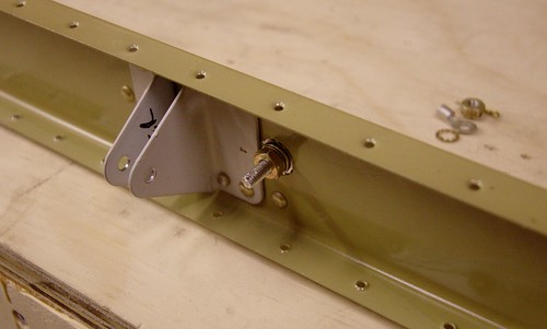
Yesterday over lunch I spent an hour and got the bond strap attachement stud attached to the top end of the vertical stabilizer rear spar.
This involved several steps. First, I test-fit the stud and its attachment hardware (including the ring terminal and castle nut). I used a sharpee to mark the footprint of the washers on the spar and doubler so that I'd know where to remove the primer coating. Also marked the appropriate place for a cotter pin hole in the castle nut. All hardware was removed and a Dremel drum sander was used to rip off the primer from where the washers will contact the spar and doubler. This should make for an excellent electrical connection.
Next, all of the aft-side hardware was attached to the threaded rod stud and placed into the hole. A bead of red threadlocker was added to the forward side of the stud and the forward-side hardware tightened down into place. The aft-side hardware was then removed, threadlocker added to this side, and the permanent hardware was tightened back into place. When the threadlocker cures (24 hours), the bonding stud will be permanently in place. I went ahead and added a generous blob of epoxy gel to the foreward side to further hold everything in place. On the aft-side, where the strap ring terminal will attach, I had to be more judicious with the epoxy. I just added enough to cover the exposed aluminum under the washer and add some additional locking to the nut. The top surface of the nut was kept clear of epoxy since this is the electrical bond surface for the strap hardware.
With the bond stud in place, it was finally time to add the skin to the vetical stabilizer. Initially, this just involved clecoing the skin in place. I went ahead and detached the lower nose rib so that the initial rivets in the middle nose rib could be bucked.
Today over lunch, Bob came down and we spent an hour doing rivets. This was Bob's first experience with riveting, and the first rivets to do on that middle nose rib are probably some of the most akward and difficult rivets in the whole plane. But he was very good with the bucking and we managed to get all three nose ribs completed and looking good.
There were a couple small mistakes, minor smilies, etc, but nothing that I'm concerned about. One of them is below the empennage fairing line and the other is small enough that I think a bit of filler will cover it when it comes time to paint.
14 Nov 2009
Yesterday I added the 32 small universal rivets connecting the vertical stabilizer rear spar flanges to the spar caps below the skin. These were straightforward as they can all be squeezed, though I managed to get a few where the head wasn't seated all the way down correctly. The difficulty is that with the pneumatic squeezer and the geometry of the piece, the cupped head of the rivet has to go on the moving part of the squeezer. Thus, as the squeezer is engaged, the entire device has to move relative to the spar flange, rather than the squeezer staying put and just the flush end ramming into the back of the rivet. If this movement isn't conducted just right, the rivet can be pushed out of position a bit before the two ends of the squeezer start applying equal force, resulting in a poorly-seated rivet. I haven't figured out the solution to this yet. For now, I have a few rivets that need to be drilled and re-done.
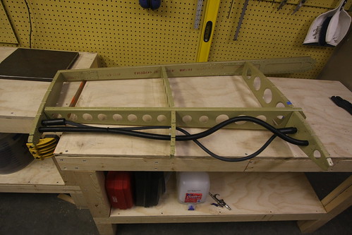
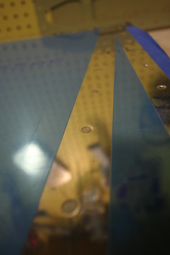
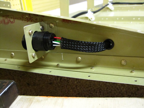
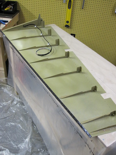
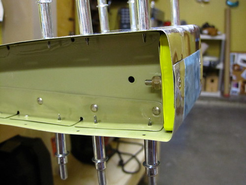
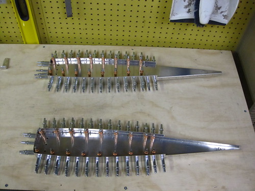
While waiting for assistance to buck the rest of the skin rivets, I pulled the slack out of the wiring conduit, preventing it from rubbing against anything inside the plane. I put some black RTV on a gloved finger and stuck it through the forward-most lightening hole of the lower nose rib so that I could make a vibration-cancelling fillet where the conduit passes through the doubler, but not visible from the outside. Here is a picture of the inside of the vertical stabilizer. The wire bundle and conduit in the lower-front cavity can be seen through the lightening holes:
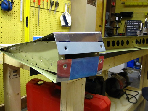
Last night, Bob came by with a pizza and we did Dinner & Rivets (soon to be a recurring feature, I hope). Bob acted as the bucking bar placement specialist as we drove the final 218 rivets into the skin. Here he is during the cumbersome bucking of the upper forward spar rivets, which require pealing back the skin a bit and wedging your arm inside.
After about three hours of work, the vertical stabilizer was done! (at least as far as Section 6 of the plans is concerned...)
I'm pretty happy with how it turned out. We went through and examined every visible rivet and marked seven that needed to be replaced because they weren't seated correctly. There are a handfull of smilies and small deformities in the skin from one mistake or another, but nothing that raises a safety concern. I think most of them will be magically whisked away when I give it a once-over with filler prior to priming. Remaining tasks for the vertical stabilizer are now:
- Fix the seven bad rivets
- Attach to the rest of the empennage (this happens in Section 11)
- Add the tip fairing (this happens in Section 12)
- Outer surface treatment (filler, primer, paint, etc; this happens when the plane is structurally complete)
15 Nov 2009
Spent a few hours this afternoon getting some of the rudder parts riveted together. This had been on hold ever since I broke my back-rivet set last week. A replacement came in the mail on Friday and today I put it to use.
With all of the stiffeners attached to the skins, I moved on to the wire tie anchors needed to securely route wires from the lower fairing up to the rudder trim servo. These were the same anchor parts I used to pass wires and conduit through the lightening holes in the vertical stabilizer. In retrospect, I put them on the wrong side. I attached them to the left-side skin because that's what I had on the bench at the time. However, the right-side skin is where the rudder horn and lower rib get attached before the two sides are sewn up. If I had put them on the right side, I could run the entire wire bundle before beginning the pro-seal attachment activities (which are going to be hectic enough as it is with its limited pot life). Now, I'll have to do the wire-tieing as I go during the pro-seal ordeal.
Next I attached the rudder horn and lower rib to the right-side skin. This involved using the squeezer and the rivets came out very well. The only difficulty was the forward-most rivet, which the pneumatic squeezer can't reach. I'm not sure how to proceed on that one. With the body of the squeezer on the outside of the skin, the squeezer runs into the rudder horn. With the body of the squeezer on the inside of the skin, it runs into the opposite flange. I can't back-rivet it because the rivet gun will also run into the opposite flange. I can't use an offset set because they're all cupped. Have to think about this one. Perhaps someone makes an offset flush set?
With the horn attached (with all but one rivet), I went ahead and blind riveted the shear clips on. This was my first experience with blind rivets; they're really easy and fun to watch. It's a shame they aren't flush or structural.
16 Nov 2009
With where I left off last night, the rudder is now at the point in the instructions where the next step is to rivet the two sides together, rendering the insides largely inaccessible. With that in mind, it was time to take care of the internal customizations.
The first thing I did was put a circular plastic connector on the rudder trim servo wires. These are tiny 26awg wires which I had to buy special crimp pins for. The connector came out very well.
I was going to do the wiring harness that connects this CPC to the one riveted to the bottom of the lower rudder rib, but realized that I had neglected to get sockets appropriately sized for the 20awg wires I recently purchased for this harness. I went ahead and ordered the necessary parts (from mouser.com, of course) and the wiring harness will have to wait.
I also took a look at the static wick attachment options. There's going to have to be some rivet surgery; I should have thought about this before I riveted on the upper stiffeners. Each of the two wicks will need to have two nutplates installed on the left skin. The holes in the Dayton Granger 16165 wicks are sized for a #10 screw, so I ordered some AN525-10R6 and AN525-10R7 washer head screws from Aircraft Spruce in addition to some anchor nuts with elastic inserts. If I can fit these nutplates inside the very narrow trailing edge of the rudder, then my wicks will be removeable with a simple screwdriver when required for replacement or aesthetic snobbery. However, until this hardware shows up, the wicks are on hold as well.
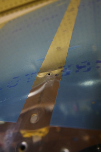
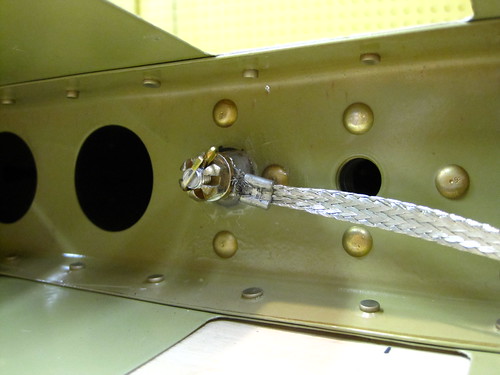
What I did have hardware for was the rudder bonding stud— the counterpart to the one I installed in the vertical stabilizer rear spar last week. This one is a clone of the VS stud and was prepared and installed in basically the same way. Here's a shot showing where I put it:
Unlike the VS stud, this one did not take the place of a rivet; I simply made a new 3/16" hole in between the upper most rivets on the doubler for the upper hinge nutplate on the rudder spar. On a whim, I measured the resistance between the top of the bonding stud and one of the adjacent rivets. It was 0.2 Ohms. From the top of the stud to the far end of the rudder spar was 4 Ohms.
19 Nov 2009
Today the pins and sockets which allow me to finish the rudder wiring arrived (along with some oops rivets to fix the two remaining biffed rivets on the VS). I bit the bullet and moved the wire tie anchors over from the left skin to the right. This allows me to pre-wire the rudder trim harness before having to button up the two sides of the rudder.
I stuffed a piece of 3/8" braided sheath through the snap bushing in the lower rudder rib, then fed the five 20awg wires through. The sheath was then wire-tied to the wire tie anchors in such a way that the sheath never touches metal anywhere (except on the free end, for now).
I put CPC pins on the lower end of each and fed them into the CPC that had been riveted into place when I fabricated the lower rib.
The upper end I am leaving unfinished until the time comes to actually wire up the servo. There will be an access plate cut into the left-side skin for getting at the servo, and through this hole I can finish the connector on the other end of this harness. In the meantime, I applied a pair of adhesive wire-tie anchors to the inside of the left-side skin, just aft of the spar. I'll tied the wires in place with these, keeping them out of the way for the final assembly of the rudder. When the time comes to cut rudder modifications into the rudder, I'll free the wires and run them through the lightening holes of the rudder to keep them out of the way.
The next task was to figure out how to attach the static wicks. I purchased some one- and two-lug anchor nuts with elastic inserts sized for a #10-32 thread. The #10 fits perfectly through the holes in the Dayton-Granger 16165 static wicks. Aircraft Spruce sells an AN525-10R7 washer-head screw that matches the #10-32 thread, has a head perfectly sized to hold the static wick down, and is exactly the right length so that the last thread protrudes out of the elastic insert but no further. This will allow me to put the nutplates as far aft as possible, where space comes at a premium. Here is an overhead view of the two nutplates I intend to use for the upper static wick just sitting in place and a wick next to them:
And here is the side view of the same anchor nuts showing how they fit within the rudder headroom next to the stiffener angle:
Note that these tests were done on the right-side skin because its stiffener was slightly taller at this end and was a more accurate representation of the available headroom. The wicks will actually be attached to the left-side skin, however, to add to the right rudder effect.
The next task will be to drill out the holes for the anchor nuts and countersink the rivet holes on the outside, allowing for AN4263-4 flush rivets to be back-riveted in.
22 Nov 2009
A couple days ago I finished up work on the rudder static wicks. First I drilled the holes out for the nutplates. I learned the hard way that the right order to do these in is to drill the large hole first, then attach the nutplate with a bolt and use the nutplate as a template for the two rivet holes. Trying to drill the smaller holes first, cleco them in, and then drill through the threaded part of the nutplate proved infeasible and I ended up having to enlarge the larger holes on one of the wick emplacements. Big holes first.
With the holes drilled and deburred, I set about countersinking the rivet holes on the outer side. They have to be flush because the flat static wick surface lays right across the top of them. Unfortunately, the skin is quite thin and the stiffener isn't exactly thick, either. Furthermore, with the stiffeners already in place, there wasn't a good way to get the holes level under my drill press. So I countersunk manually using my deburring tool. The countersinks aren't perfectly circular, but you have to get really close and be looking for it to notice that. I was able to back-rivet all of the rivets, except the spring sheath on my new back rivet set is made of poly instead of metal so it has to be thicker. The rivets adjacent to the threaded part of the anchor nuts ended up cleating a bit because the thicker sheath prevented the set from making full contact. This would be one advantage to the Isham Inc. backrivet set (the one I broke); it wouldn't have had this problem. I didn't worry too much about the cleated rivets, though, since these aren't structural and once the wicks are screwed in, they're redundant entirely.
With the anchor nuts attached, the static wicks screw right on from the outside. They're replaceable if needed, and removable if I want the plane to have cleaner lines for a photo op or something. Very happy with how this turned out.
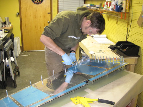
Today, Bob came down and we spent a couple hours dealing with the first dreaded task of the entire plane: the rudder trailing edge. This, of course, involves the first usage of ProSeal (or its equivalent that Van's sold me) on the aircraft. This is nasty stuff; it sticks to everything and smells pretty bad to boot. I went through four pairs of nitrile gloves in a bit over an hour. I used a little hard plastic squeegee to apply the sealant to the extruded aluminum piece. Here's what it looked like once I got both sides applied and the edge piece layed on the skin.
Getting clecos to stay in the trailing edge holes proved to be really difficult. Certain holes just seemed to be slightly oversized from the dimpling or something and wouldn't hold a cleco. Others would hold a cleco in one orientation but not if it twisted. Others would hold some clecos but not others.
Bob held the skin back while I did all the internal blind rivets and added clecos to the trailing edge. I tied the rudder trim wire bundle to an adhesive wire tie anchor on the left skin to keep it out of the way of this process.
In the end, with the two skins attached via the stiffeners and the sealant, I was only able to get about 85% of the clecos into the trailing edge to stay.
I put a board on top of the skin to weigh it down and put some heavy stuff on top of that, but with all the missing clecos there were still some places where the trailing edges weren't as tight as I'd like. So Bob and I made a 9:30pm run to the grocery store and picked up 100 clothes pins for $4. They were small ones without a lot of clamping force, so I didn't have to worry about denting the aluminum or anything like that. But it was enough to bring the trailing edge skins down onto the extruded aluminum piece everywhere. We used a ton just to be safe:
Now I wait for two days while the sealant cures. This is convenient, because this is Thanksgiving week coming up and I have Wednesday, Thursday, and Friday off. So two day week, and a two day pause required for curing. As soon as my vacation rolls around, I'll be ready to work again (though my first cross country flight training is Wednesday morning, so the rudder work will be delayed a bit by that).
26 Nov 2009
Happy Thanksgiving. Before (and after) doing The Meal™, I got some work done on the rudder.
I didn't have an assistant to help me with bucked rivets, so I tried to do everything I could that involved blind rivets first. This began with the connections between the rudder spar and the shear clips. However, before I did those I wanted to do some final tending on the rudder trim wire harness. I put a final wire tie into one of the adhesive anchors on the inside of the left-side skin.
Then I put the spar in place and routed the wire harness through the nearest lightening hole. The idea is that the wire harness will be out of the rudder trim bay when I go to make the cuts for the access panel and the trim tab itself. For the time being, I'll just run the wires down the forward side of the spar, between the spar and the rounded leading edge. Once the cuts are made in the trim area, I'll pull the wire harness back through the lightening hole and tend the end. With the wiring taken care of (for now), the spar's blind rivets went really quickly.
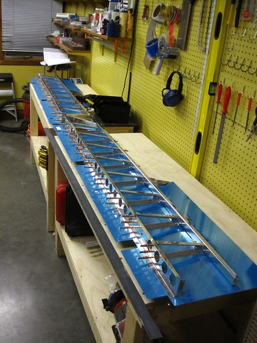
With that, the only remaining task on the rudder that I could accomplish without an assistant was riveting the trailing edge. I had been somewhat apprehensive about starting this because there's a lot of talk on builder's logs about it being 1) difficult and 2) critical. I decided to go with a variation of the method described on Tim Olson's website—to make a long back-rivet plate out of a 6' piece of 2"x2" angle iron and cleco the rudder to it.
I started by screwing the angle iron into my work bench such that the top surfaces of both were flush. Then I used the elevator trailing edge extrusion as a template to drill holes into the top surface of the angle iron. I drilled every 10th hole plus one at the end so that there would be clecos at each end of the rudder, for a total of 7 clecos holding the rudder onto the plate.
With the holes in place, I put rivets into every other hole of the trailing edge, secured them with rivet tape, then flipped the rudder over and attached it to the angle iron with clecos.
I just used a flush set on the shop side of the rivets and they came out OK. With the first side's rivets complete, I removed the clecos, put rivets in the remaining holes (with the exception of the seven cleco holes), taped them, flipped the rudder over, and back-riveted these new rivets. This left just the seven holes to be done without the aid of cleco attachment to the back-rivet plate. This was not a problem and they didn't introduce any bend to the trailing edge.
All-in-all, the trailing edge was exceptionally easy with this method and I got a great-looking, unwavy, un-bend trailing edge out of it. Highly recommended for future builders.
28 Nov 2009
Big day for the rudder.
Nina gave me a hand in the morning bucking the rivets connecting the skins to the rudder spar. We also finished off the lower rib flange rivets and the rivets attaching the two halves of the upper rib. With that, it was time to do the rudder counterweight.
The lead weight was clamped into place and the skins bent around it by hand. After that, a bending jig was assembled out of blocks of wood and C-clamps.
From there, the skins are bent into tight angles so that they will envelope the lead brick. Before inserting the lead brick, I added a couple of small customizations not given in the plans. First, I covered the lead brick's edges in a ring of electrical tape so that there will be no exposed lead in the final part.
The other minor change was to prime the piece of skin that is covered by the other side skin on the forward side of the lead brick. I scuffed this area with scotchbrite then used a Krylon spraycan primer.
Once these modifications were made, the lead brick was attached to the rudder permanently.
With the counterweight complete, it was time to close up the leading edge of the skins. However, before this was done I had to attach the bonding strap to the my custom bonding stud. This was a straightforward crimp of the strap into a ring terminal, and adding a castle nut and cotter pin to hold it in place.
The leading edge skin tabs were rolled using a 1" diameter broom handle. The section of the skin that gets overlapped was again treated with primer, just as was done for the counterweight skins.
Once all the match drilling and priming was complete, the leading edge was cleco'd up again and then the blind rivets were put in place. This is a quick operation.
With that, the rudder as specified in Section 7 of the plans was complete.
I placed the rudder down next to the vertical stabilizer to check the fit. Unfortunately, the VS bonding stud runs into the leading edge curve of the rudder. I'll have to cut off a bit of the upper leading edge of the rudder to make room for this, but that's not a terribly difficult modification.
Of course I haven't made the mechanical modifications for the rudder trim system either. This will be a major undertaking and entirely off the reservation as far as the plans are concern. However, I do not need to make this modification immediately; I'll probably save it for some time when I'm waiting for a future kit to ship or for more money to be made so that I can buy the next kit. Rudder trim is to be continued; for now, the rudder is "done."
29 Nov 2009
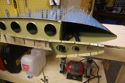
The first thing I did today was finish up a few remaining tasks on the vertical stabilizer and rudder. The vertical stabilizer just needed a couple of rivets put in. They were at the bottom of the foreward spar and I had biffed them the first time through, then really mangled the holes trying to drill them out. My solution was to get some big 3/16" AN470 rivets to fill the holes. I drilled out the new big holes with my right-angle drill kit, inserted the big fatty rivets, and drove them home with my 3x rivet gun. No problem. Aside from being huge, they look great. They're probably stronger than the original rivet, so as far as I'm concerned its an improvement. I now pronounce the vertical stabilizer complete until Section 12 (fiberglass fairings) comes along. I taped up the holes in the VS to prevent bugs from getting in, and put it out in the shed for long-term storage.
Next I put a few last touches on the rudder. First I cut a small section out of the leading edge above the upper hinge opening to make clearance for the vertical stabilizer's bonding stud.
The cut was made with a dremel cutoff wheel and was straightforward. I cleaned up the edges with a file and an edge deburring tool. As a result of the cut, the rudder's bonding stud is now directly accessible, which may aid in future inspections and maintenance, though the whole point of not having a more compact bonding attachment on the vertical stabilizer was because the rudder attachment would be harder to reach. Now they're both about the same difficulty to work with... so I'm not sure if there would be a better arrangement if the assumption was made up front that this cut would be made.
Something to think about for future builders wanting to do some bond strap work, I suppose. Regardless, I'm happy with how it turned out. The VS and rudder fit together perfectly now.
I taped up the holes in the rudder for the same reason as I had in the VS, and while doing so found three rivets at the base of the rudder spar that I had overlooked yesterday. Whoops! Not a problem, they were still fully accessible so I just squeezed them in and that was that. The rudder is now complete until Section 12 (or until I decide to make the rudder trim cuts, whichever comes first).
Now it's time to move on to the next section. The next section of the plans is the horizontal stabilizer. But because I still have the trailing edge back-rivet plate installed on my workbench and because I don't relish the idea of working with a 12' long assembly, I decided to do the elevators first.
The first step, as with all of the empennage subassemblies, was to do some bandsaw work. I cut apart the rib halves and the shear clips and then deburred everything. Step 2 on the first page of the elevator plans just says "deburr all parts." This step takes a long time. However, once it's complete, the elevators start to take shape remarkably quickly. First up was the ribs:
Next was the tip counterweight assemblies. These took some time because the flanges on the steel pieces didn't line up as well as the aluminum parts I'm used to. Had to use a ton of clecos to get everything to stay in place, too.
Next I did some drilling on the shear clips and tip assemblies. Then some bends were made to the close out tabs on the four elevator skin sheets. After that, the skeleton starts to come together in short order. The forward and rear spars as well as the ribs all get cleco'd together and to the bottom skins. Suddenly, I had what looked somewhat like elevators on my workbenches.
The next step is a bunch of match drilling, which I didn't feel like doing, so I called it quits here for the day.
| <-- October 2009 | December 2009 --> |